Pliers

a technology of pliers and pliers, which is applied in the field of pliers, can solve the problems of reducing consuming a large amount of metal materials, and prone to cracking of the soldered side seams of thin-walled pipes, so as to achieve convenient and economic assembly, reduce the thickness of the pipe wall, and save material costs

Inactive Publication Date: 2014-07-15
PANG HAOHUI +1
View PDF8 Cites 3 Cited by
  • Summary
  • Abstract
  • Description
  • Claims
  • Application Information

AI Technical Summary

Benefits of technology

[0006]In view of the above-described problems, it is one objective of the invention to provide a pair of pliers that are light-weighted, cheap, portable, and convenient for operation. The pliers cause no destruction to pipe ends and to soldered side seams upon processing.
[0009]Advantages of the invention are summarized as follows. The pliers can work out a boss on the pipe wall quickly and cause no destruction to pipe ends and to soldered side seams upon. There is no need for the pipe to dispose a screw thread, thus the thickness of the pipe wall reduces, the material cost is saved, and the assembly is convenient and economic.

Problems solved by technology

Typically, metal pipes are connected by using threaded connection and ring expansion connection, both of which require cutting the ends of the pipes, thereby weakening the strength of the ends of the pipes.
For the benefit of the cutting, the pipes must be manufactured to have a thick wall, thus consuming a large amount of metal materials.
Although the ring expansion connection has a low requirement on the wall thickness of the pipes, soldered side seams of thin-walled pipes are prone to crack in the process of ring expansion.

Method used


Image

  • Pliers
  • Pliers
  • Pliers

Examples


Embodiment Construction

[0015]For further illustrating the invention, experiments detailing a pair of pliers are described below. It should be noted that the following examples are intended to describe and not to limit the invention.

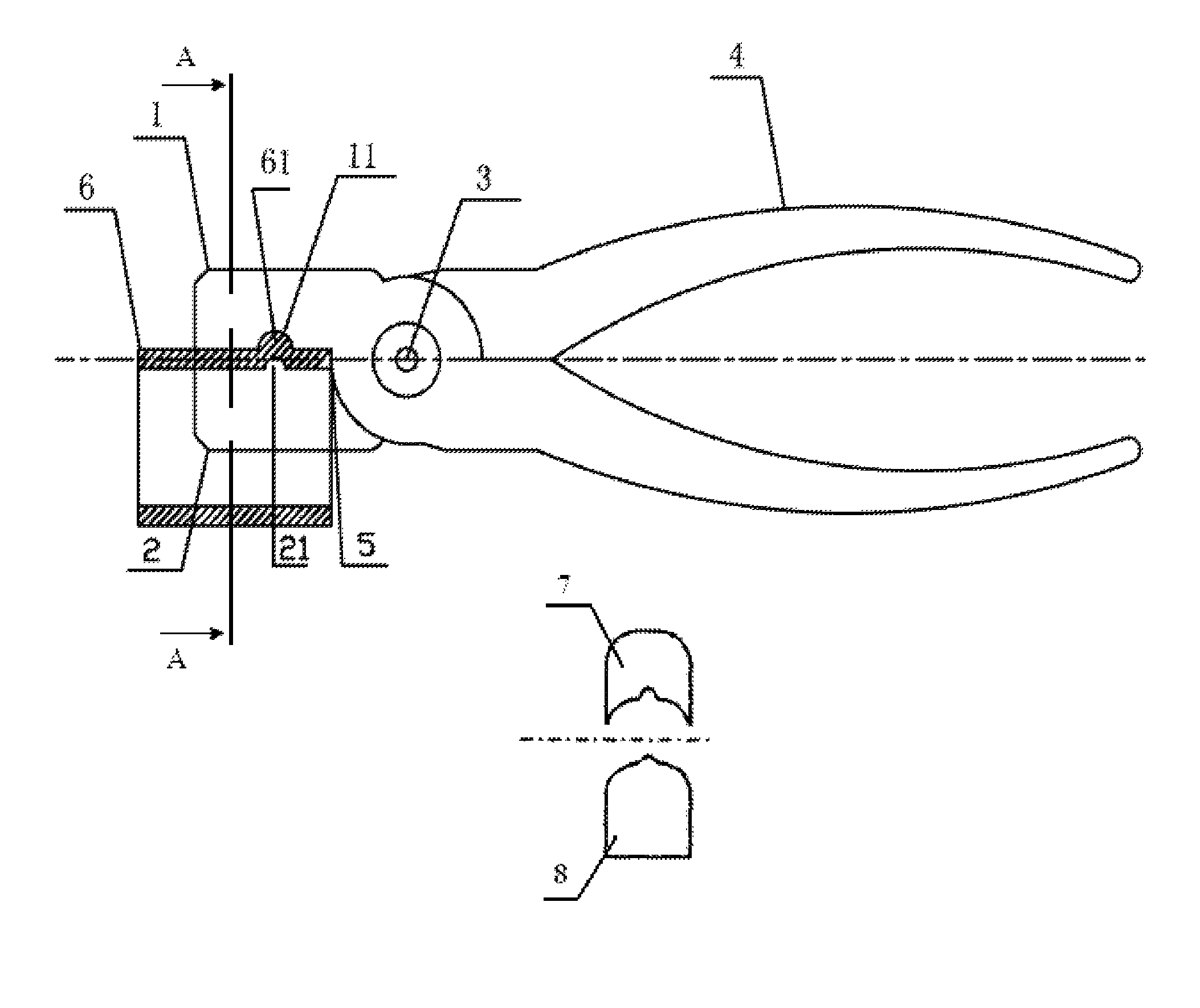
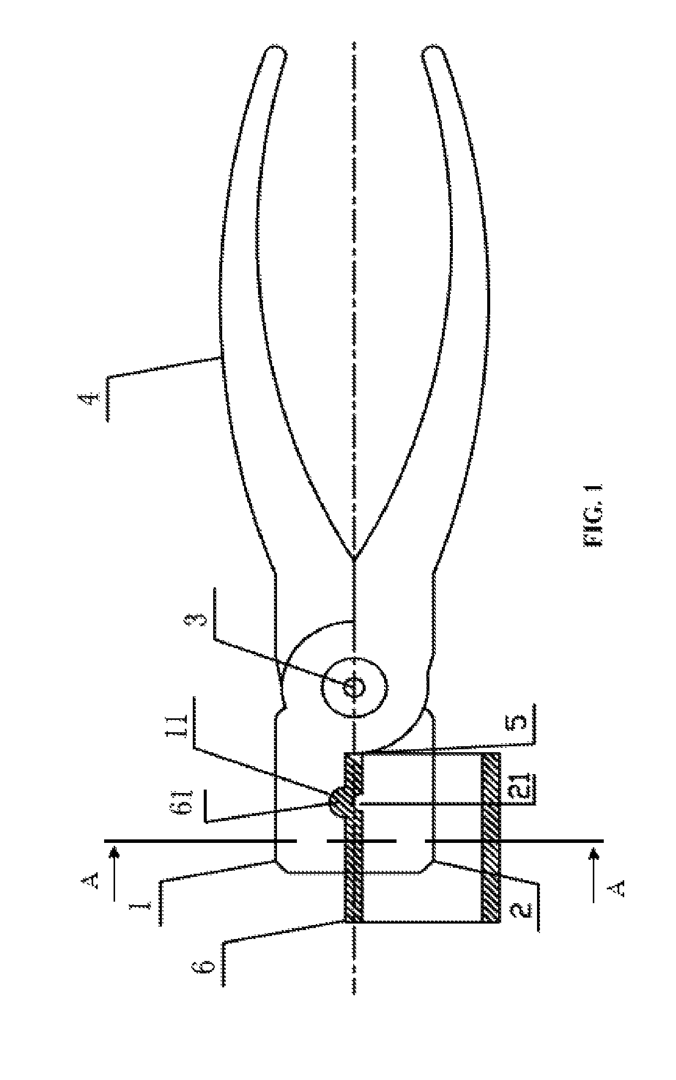
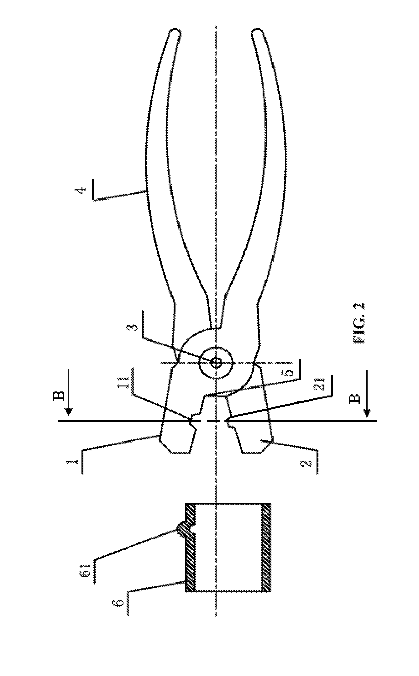
[0016]As shown in FIGS. 1-2, a pair of pliers special for producing a boss on a thin-walled metal pipe comprises an upper jaw 1, a lower jaw 2, a pivot 3, and two handles 4. The upper jaw and the lower jaw combine to form a gripping jaw capable of opening and closing. The upper jaw is in the shape of a concave arc 7, and the lower jaw is in the shape of a convex arc 8. The inner arc comprises a concave hole 11, and the outer arc comprises a convex member 21 corresponding to the concave hole 11. The two handles are integrated with the upper jaw and the lower jaw, respectively, and fixed via the pivot to form a cross connection.

[0017]Upon processing a pipe 6, the lower jaw 2 is inserted into one end of the pipe 6. The end of the pipe is tightly against the bottom 5 of the clampin...


PUM

PropertyMeasurementUnit
radiusaaaaaaaaaa
surfaceaaaaaaaaaa
strengthaaaaaaaaaa

Abstract

A pair of pliers including an upper jaw, a lower jaw, two handles, and a pivot. The upper jaw and the lower jaw combine to form a gripping jaw capable of opening and closing. The upper jaw is in the shape of an inner arc, and the lower jaw is in the shape of an outer arc. The inner arc includes a concave hole, and the outer arc includes a convex member corresponding to the concave hole. The two handles are integrated with the upper jaw and the lower jaw, respectively, and fixed via the pivot to form a cross connection.

Description

CROSS-REFERENCE TO RELATED APPLICATIONS[0001]This application is a continuation-in-part of International Patent Application No. PCT / CN2012 / 000688 with an international filing date of May 18, 2012, designating the United States, now pending, and further claims priority benefits to Chinese Patent Application No. 201110105732.3 filed Apr. 25, 2011. The contents of all of the aforementioned applications, including any intervening amendments thereto, are incorporated herein by reference. Inquiries from the public to applicants or assignees concerning this document or the related applications should be directed to: Matthias Scholl P.C., Attn.: Dr. Matthias Scholl Esq., 14781 Memorial Drive, Suite 1319, Houston, Tex. 77079.BACKGROUND OF THE INVENTION[0002]1. Field of the Invention[0003]The invention relates to a pair of pliers.[0004]2. Description of the Related Art[0005]Typically, metal pipes are connected by using threaded connection and ring expansion connection, both of which require c...

Claims


Application Information

Patent Timeline
Patent Type & Authority Patents(United States)
IPC IPC(8): B21D9/08
CPCB25B7/02B21D39/046B21D17/02B21D22/04
Inventor PANG, HAOHUI
Owner PANG HAOHUI
Why Eureka
Try Eureka