Tire pressure sensor mounting system

Inactive Publication Date: 2014-07-15
BROWN HOWARD
View PDF16 Cites 11 Cited by
  • Summary
  • Abstract
  • Description
  • Claims
  • Application Information

AI Technical Summary

Problems solved by technology

When the valve breaks, sensor would normally have to be replaced, which

Method used


Image

  • Tire pressure sensor mounting system
  • Tire pressure sensor mounting system
  • Tire pressure sensor mounting system

Examples


Embodiment Construction

[0010]Following is a list of elements corresponding to a particular element referred to herein:

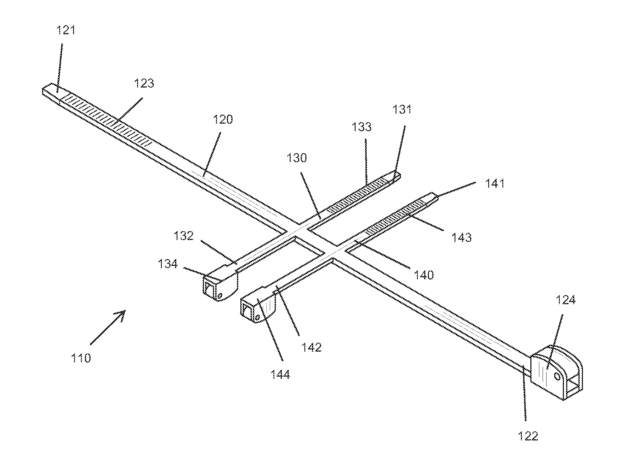
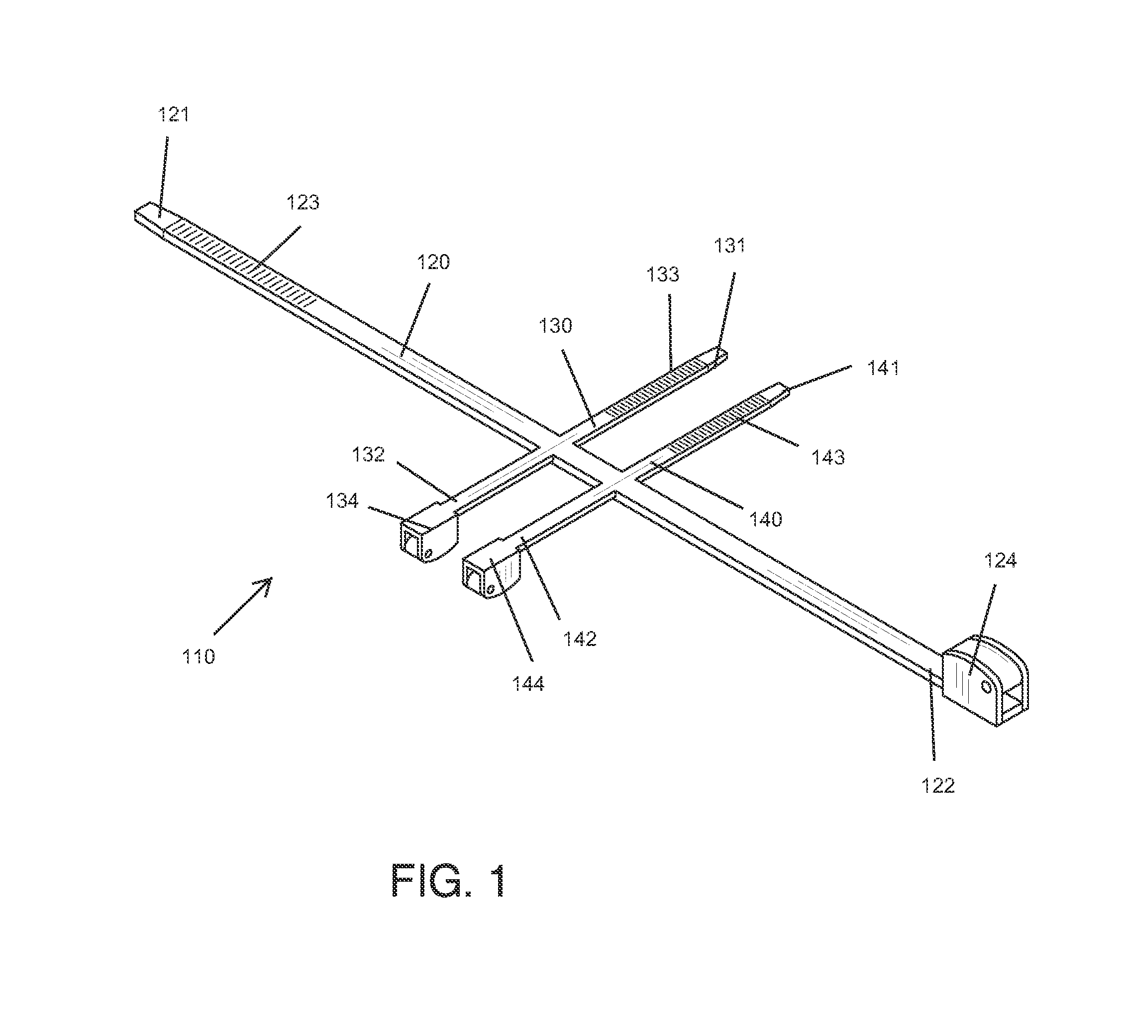
[0011]100 tire pressure sensor mounting system

[0012]110 mounting piece

[0013]120 rim strap

[0014]121 first end of the rim strap

[0015]122 second end of the rim strap

[0016]123 teeth of the rim strap

[0017]124 first lock means

[0018]130 first side strap

[0019]131 first end of the first side strap

[0020]132 second end of the first side strap

[0021]133 teeth of the first side strap

[0022]134 second lock means

[0023]140 second side strap

[0024]141 first end of the second side strap

[0025]142 second end of the second side strap

[0026]143 teeth of the second side strap

[0027]144 third lock means
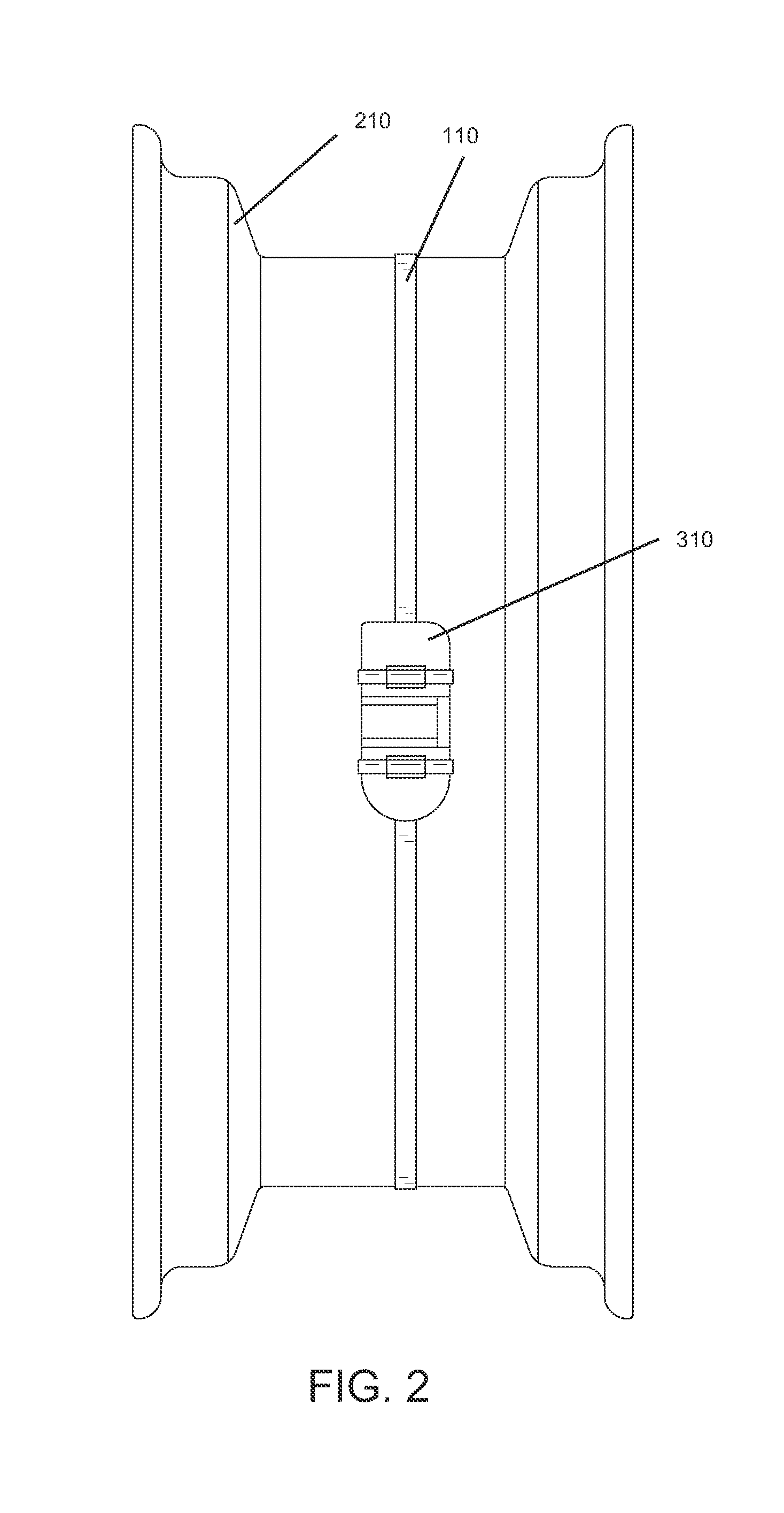
[0028]210 wheel rim

[0029]220 valve

[0030]310 tire pressure sensor

[0031]Referring now to FIG. 1-5, the present invention features a tire pressure sensor mounting system (100). The system comprises a wheel rim (210) with a valve (220) disposed on the wheel rim (210), a tire pressure sensor (310) without mechanical connecti...


PUM


Abstract

The present invention features a tire pressure sensor mounting system to mount a tire pressure sensor on a wheel rim directly. The system comprises a singular mounting piece with a rim strap and at least two side straps to securing a tire pressure sensor. The side straps are disposed along the rim strap with extension direction perpendicular to the rim strap. Both the rim strap and side straps have lock means to securely lock the tire rim and tire pressure sensor respectively.

Description

FIELD OF THE INVENTION[0001]The present invention relates to a tire pressure sensor mounting system, and more particularly to a tire pressure sensor mounting system mounted on wheel rim directly.BACKGROUND OF THE INVENTION[0002]Many modern cars now come with built-in tire pressure sensors as part of a tire pressure monitoring system (TPMS) that allow all four tire pressures to be read simultaneously from inside the car. TPMS can be divided into direct and indirect systems. Direct TPMS employ pressure sensors on each tire, either internal or external. The sensors physically measure the tire pressure in each tire and report it to the vehicle's instrument cluster or a corresponding monitor, sometimes also the temperature inside the tire. These systems can identify under-inflation in any combination, of one tire or all four, simultaneously. Typically, the sensor is connected to a tire valve. When the valve breaks, sensor would normally have to be replaced, which is time-consuming due to...

Claims


Application Information

Patent Timeline
IPC IPC(8): G01M17/02B60C23/00B60C23/04G01M17/03
CPCG01M17/03B60C23/0408G01M17/02B60C23/0493B60C23/00B60C23/0498B60C23/04985
Inventor BROWN, HOWARD
Owner BROWN HOWARD
Why Eureka
Try Eureka