

Tire air pressure estimating apparatus
a tire air pressure and estimating technology, applied in the direction of pressure difference measurement between multiple valves, digital computer details, instruments, etc., can solve the problems of lowering the power spectrum level of resonance frequency, difficult vibration phenomenon of tires, and inability to accurately estimate tire air pressur
- Summary
- Abstract
- Description
- Claims
- Application Information
AI Technical Summary
Benefits of technology
Problems solved by technology
Method used
Image

Examples
first embodiment
[First Embodiment]
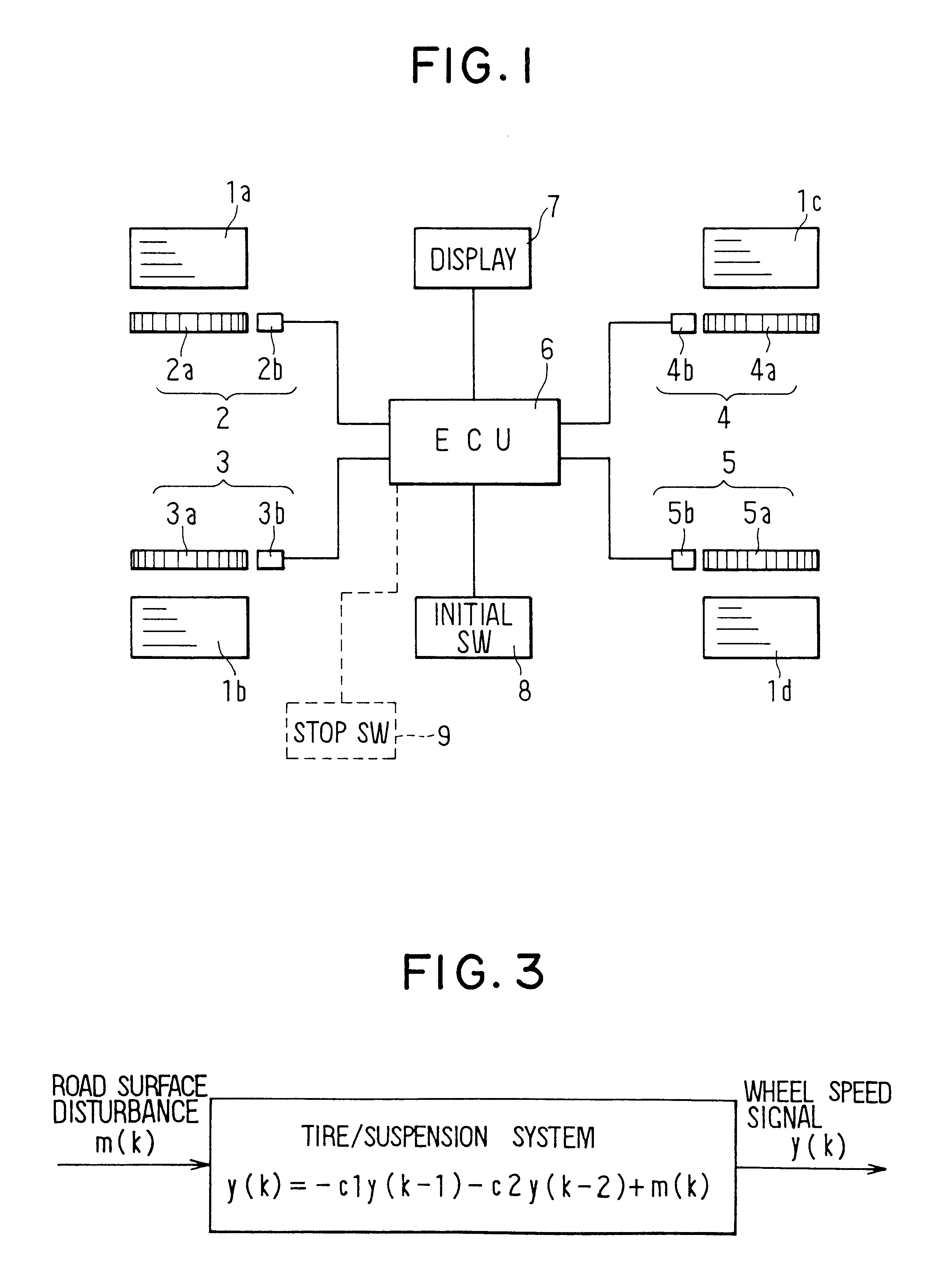
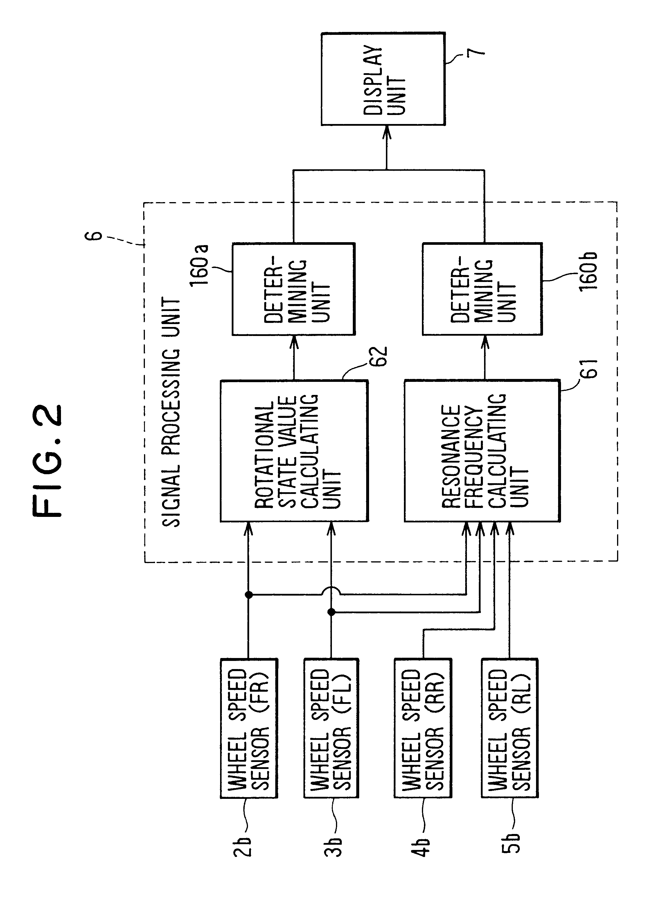
FIGS. 1 and 2 show a tire air pressure estimating apparatus according to the first embodiment of the present invention.
As shown by FIGS. 1 and 2, wheel speed sensors 2 through 5 are installed to respective tires 1a through 1d of a vehicle. The respective wheel speed sensors 2 through 5 are composed of rotors 2a through 5a and pick-up coils 2b through 5b. The rotors 2a through 5a are coaxially mounted on a rotary shaft (not illustrated) of each of the tires 1a through 1d to rotate along with the respective tires 1a through 1d, and are made from disc-shaped magnetic bodies. The pick-up coils 2b through 5b output alternating current signals respectively in correspondence with rotational speeds of the rotors 2a through 5a, that is, the tires 1a through 1d.
The alternating current signals output from the pick-up coils 2b through 5b are fed to a known electronic control device (hereinafter, referred to as ECU) 6 having a waveform shaping circuit and a microcomputer compri...
second embodiment
[Second Embodiment]
An explanation will be given of a second embodiment in reference to FIGS. 14 and 15.
In the second embodiment, when tire air pressures of drive wheels are estimated based on the corresponding tire resonance frequencies calculated from vibration components of drive wheel speed signals, the frequency ranges of the vibration components are divided in two ranges, and signal intensities in the respective frequency ranges are calculated. The frequency range from which the resonance frequency is extracted is selected based on the signal intensities.
An explanation will be given of the second embodiment in reference to a flowchart of FIG. 14. It is to be noted that the flowchart of FIG. 14 is carried out in respect of drive wheels.
Steps 10 and 100 are the same as those which have been described in the first embodiment, and an explanation thereof will be omitted.
At steps 801 and 802, filter processing is carried out so that signals of frequencies other than frequencies inclu...
third embodiment
[Third Embodiment]
The third embodiment will be explained in referring to FIGS. 16, 17 and 19.
In the third embodiment, when tire air pressures of drive wheels are estimated based on the corresponding tire resonance frequencies calculated from vibration components of drive wheel speed signals, a vibration input intensity is calculated from vibration components of a tire vibration phenomenon caused by vibration input from a road surface. The frequency range from which the resonance, frequency is to be extracted is selected among a plurality of frequency ranges based on the vibration input intensity.
FIG. 16 shows a flowchart carried out in respect of driven wheels. In FIG. 16, since steps 10 and 100 are the same as those in FIG. 4, the description thereof is omitted.
At step 821, a filtering process is carried out so that signals of frequencies other than frequencies including the vibration components of the tire vibration phenomenon caused by vibration input from the road surface, are c...
PUM
 Abstract
Description
Claims
Application Information