
Ramp controlled driver for series/parallel solid state lighting devices

a technology of parallel solid state lighting and driver, which is applied in the direction of electric variable regulation, process and machine control, instruments, etc., can solve the problems that series-connected oleds often suffer from individual elements, and achieve the effect of slowing the rise and fall times, avoiding or mitigating current spikes, and slowing current rise and fall times

Inactive Publication Date: 2014-07-15
GE LIGHTING SOLUTIONS LLC
View PDF22 Cites 2 Cited by
  • Summary
  • Abstract
  • Description
  • Claims
  • Application Information

AI Technical Summary

Benefits of technology

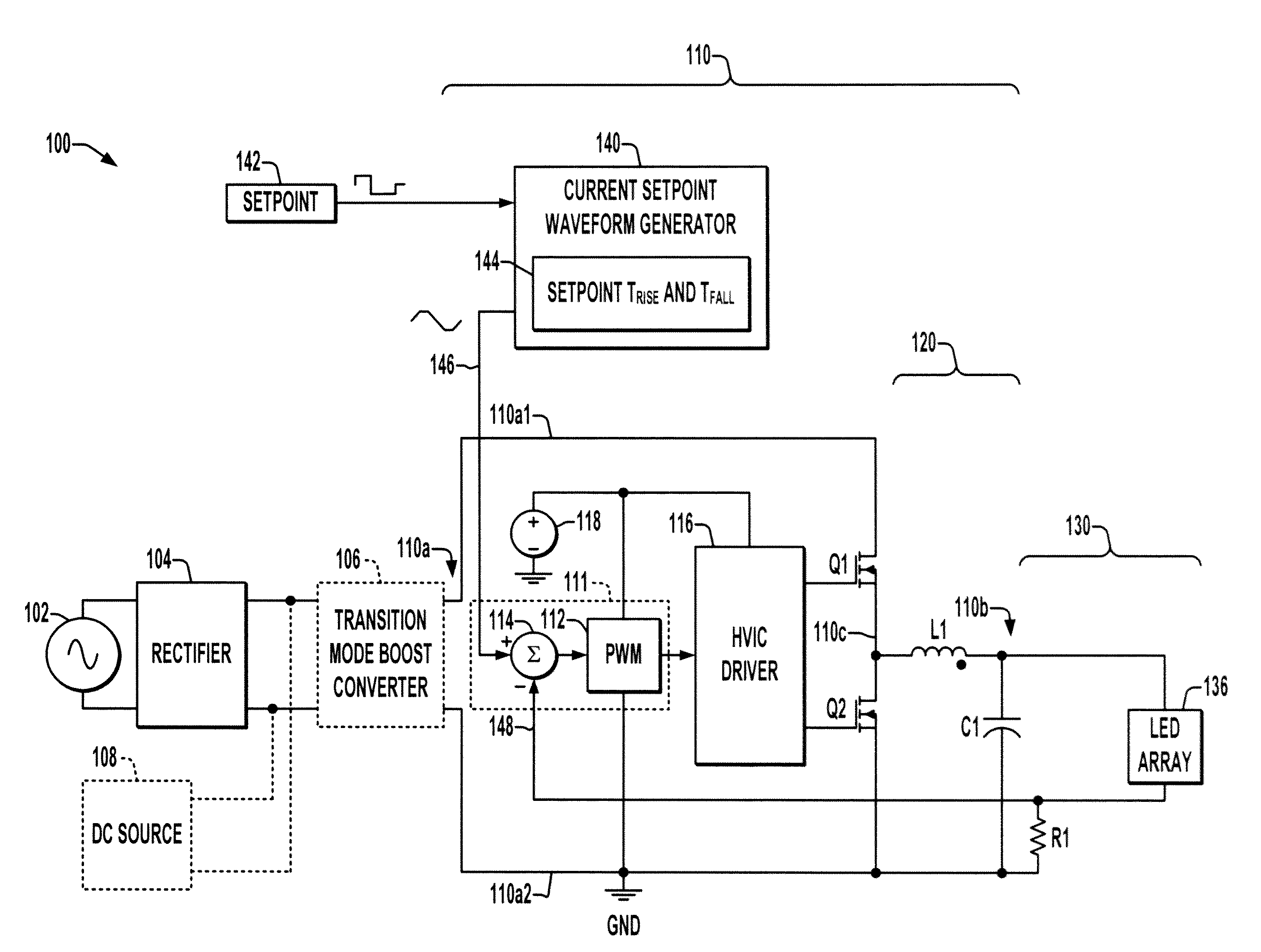
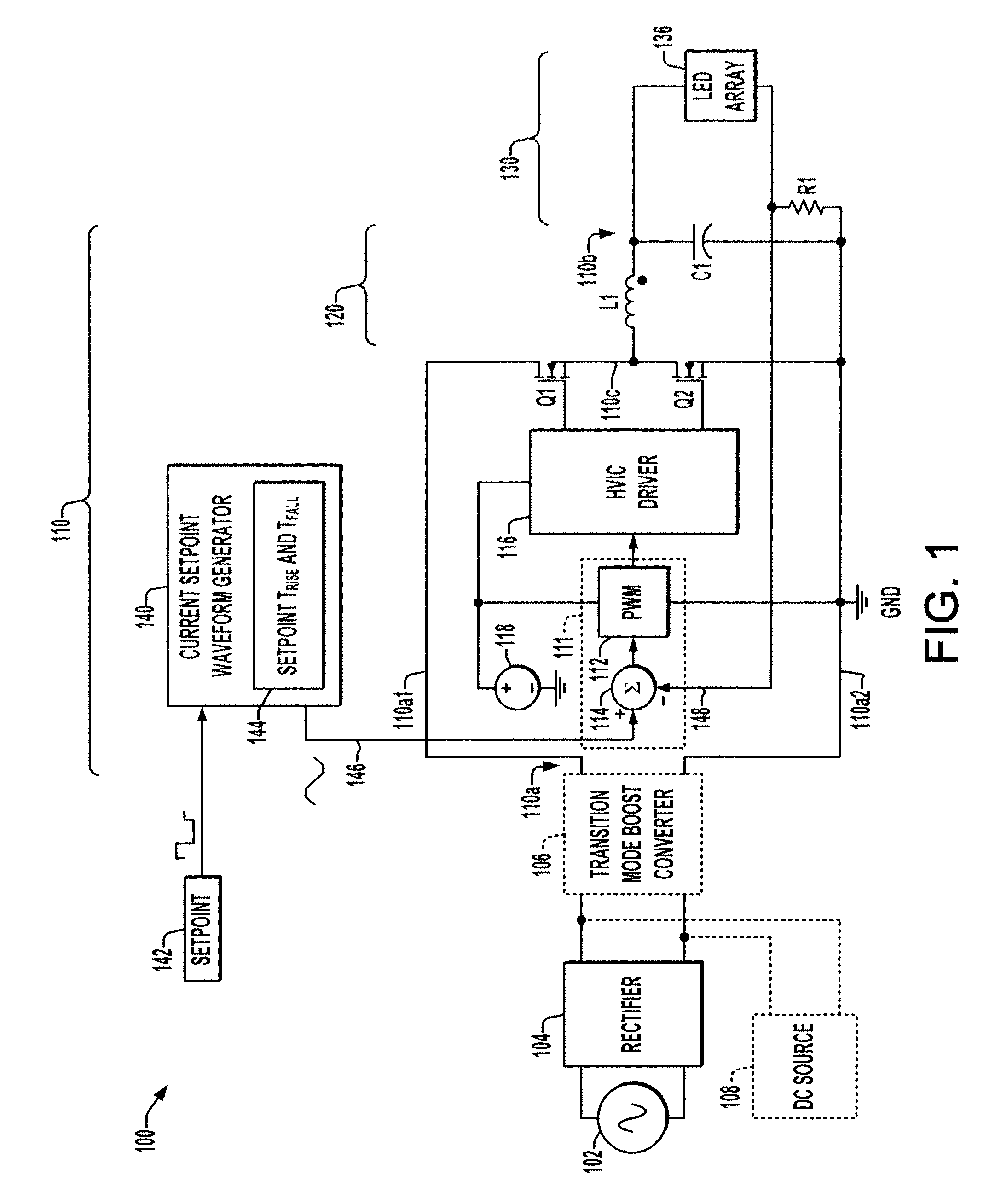
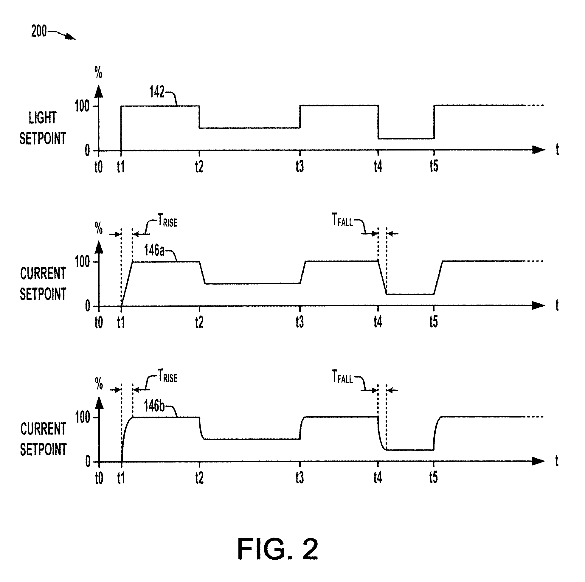
[0002]The present disclosure provides apparatus for driving OLED arrays in which a waveform generator slows the rise and fall times of the current control setpoint of a DC-DC converter stage, thus avoiding or mitigating current spikes seen by highly capacitive OLED panels of the array. This control apparatus advantageously serves to slow the rise of current when the device is turned on or anytime a lighting setpoint involves step or rapid changes to increase or decrease the lighting output. The waveform control concept may be employed to combat output current overshoot, which may be 40% of rated current absent the disclosed concepts. The improved ability to operate large capacitance outputs without excessive current spikes can advantageously mitigate premature device degradation and thus extend the usable service-life of a given lighting installation. Moreover, series-connected OLEDs often suffer from individual elements not consistently illuminating during startup.

Problems solved by technology

Moreover, series-connected OLEDs often suffer from individual elements not consistently illuminating during startup.

Method used


Image

  • Ramp controlled driver for series/parallel solid state lighting devices
  • Ramp controlled driver for series/parallel solid state lighting devices
  • Ramp controlled driver for series/parallel solid state lighting devices

Examples


Embodiment Construction

[0014]Referring now to the drawings, like reference numerals are used to refer to like elements throughout and the various features are not necessarily drawn to scale. FIG. 1 illustrates an electronic driver apparatus 100 receiving input power from an AC source 102, with a rectifier 104 providing an initial DC output. The driver 100 may optionally include a transition mode boost converter 106 (shown in dashed line in the figure) converting the initial DC to provide a boosted DC input 110a to a loop compensated WPM controlled DC-DC converter 110. In certain embodiments, the apparatus 100 may instead receive DC input power directly from a DC source 108 (also shown in dashed line in the figure), with or without a transition mode boost converter 106. The DC-DC converter stage 110 converts the DC input power 110a to provide a DC output 110b used, directly, or indirectly, for powering an OLED array 136, which may include a series / parallel combination of organic LED panels 136. The driver ...


PUM


Abstract

An electronic OLED driver apparatus is presented, which includes a DC-DC converter stage with a waveform generator generating converter setpoints with profiles having minimum rise time and fall time values.

Description

BACKGROUND OF THE DISCLOSURE[0001]Large area solid-state devices, such as organic light-emitting diodes (OLEDS), are becoming more popular for illuminating buildings, roads, and for signage and optical display applications. Large area OLEDs have large capacitances and connection of parallel OLED strings in a lighting array increases the capacitance seen by a driver circuit. In addition, the capacitance may vary as the OLED is bent or twisted because of changes in charge distribution. For a given large area lighting installation, moreover, adding further OLEDs in series requires higher drive voltages. Thus, while large area OLED installations typically include series / parallel configurations, practical limitations exist for the number of series-connected OLEDs that can be driven and for the number of parallel-connected strings of series OLEDs. Thus, a need remains for improved techniques and apparatus for driving large area OLED arrays.SUMMARY OF THE DISCLOSURE[0002]The present disclo...

Claims


Application Information

Patent Timeline
Patent Type & Authority Patents(United States)
IPC IPC(8): G05F1/00H02M1/00H02M3/156H05B33/08H05B44/00
CPCH05B33/0815H02M3/156H02M2001/0025H05B33/0896H05B45/60Y02B20/30H05B45/38H05B45/3725H02M1/0025H05B45/37
Inventor NERONE, LOUIS R.AURONGZEB, DEEDER
Owner GE LIGHTING SOLUTIONS LLC
Learn More