Vehicle control device

a technology for controlling devices and vehicles, applied in the direction of electric control, vehicle sub-unit features, machines/engines, etc., can solve the problem of fuel efficiency drop

Active Publication Date: 2017-11-28
TOYOTA JIDOSHA KK
View PDF33 Cites 0 Cited by
  • Summary
  • Abstract
  • Description
  • Claims
  • Application Information

AI Technical Summary

Benefits of technology

[0007]If an up-shift of a change gear ratio in the automatic transmission is executed when switching to the supercharged lean combustion mode from another combustion mode, an engine rotation number decreases with the execution of the up-shift and hence the rise of the supercharging pressure may be delayed. In other words, in the case described above, the transition to the supercharged lean combustion mode is delayed and the other combustion mode is maintained, and consequently, the fuel efficiency lowers.

Problems solved by technology

In other words, in the case described above, the transition to the supercharged lean combustion mode is delayed and the other combustion mode is maintained, and consequently, the fuel efficiency lowers.

Method used


Image

  • Vehicle control device
  • Vehicle control device
  • Vehicle control device

Examples


first embodiment

[0023

[0024]Schematic configuration of vehicle

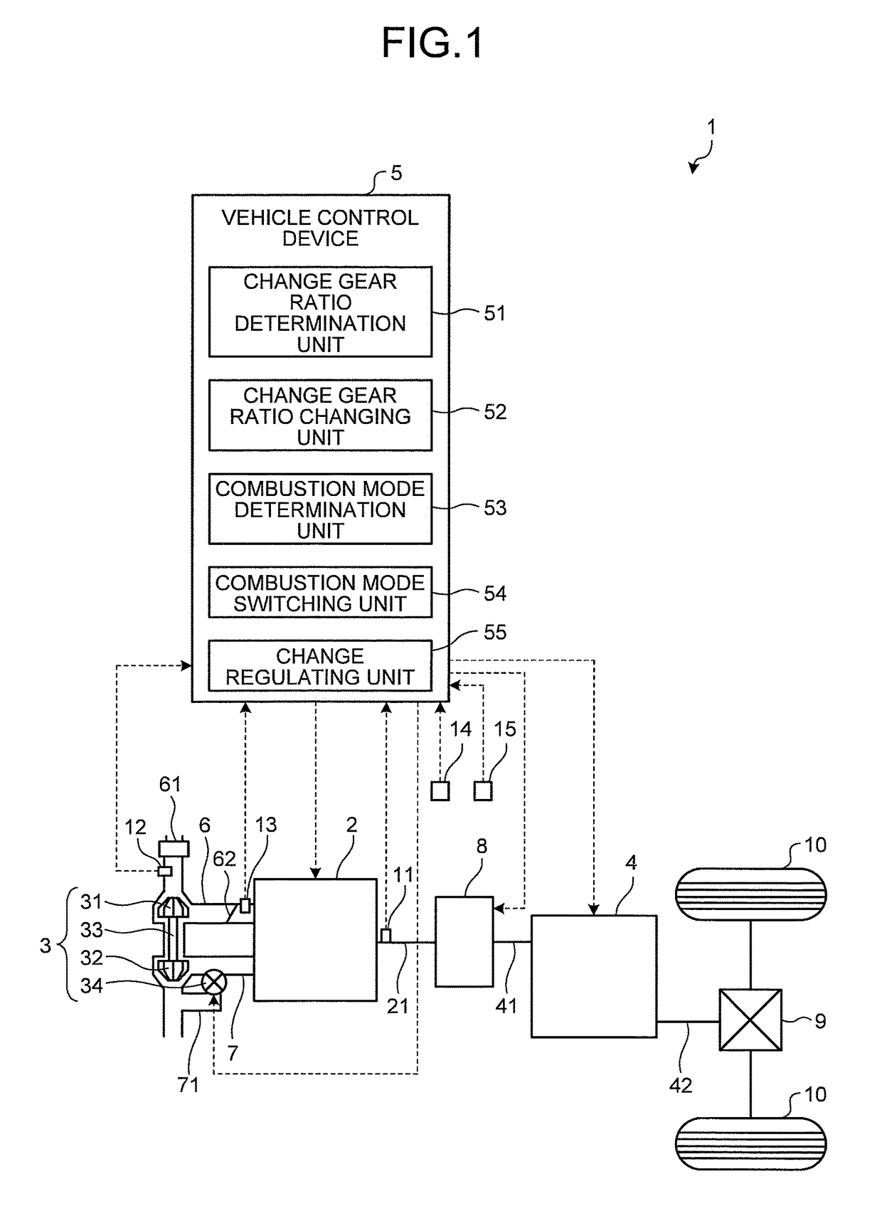
[0025]FIG. 1 is a diagram schematically illustrating a configuration of a vehicle 1 according to a first embodiment of the present invention.

[0026]The vehicle 1 enables a combustion mode of an engine 2 to be switched to various combustion modes according to an operation state of the engine 2. As illustrated in FIG. 1, the vehicle 1 includes the engine 2 with a supercharger 3, an automatic transmission 4, and a vehicle control device 5.

[0027]The engine 2 converts a combustion energy of a fuel to be combusted in a cylinder to a rotation energy of a crankshaft 21, and outputs the same under the control of the vehicle control device 5.

[0028]The supercharger 3 supplies a high pressure air to each cylinder of the engine 2 under the control of the vehicle control device 5. As illustrated in FIG. 1, the supercharger 3 includes a compressor 31, a turbine 32, a coupling shaft 33 for coupling the compressor 31 and the turbine 32, and a wastegate val...

second embodiment

[0088

[0089]A second embodiment of the present invention will now be described.

[0090]In the following description, the same reference numerals are denoted on the configurations and steps similar to the first embodiment described above, and the detailed description thereof will be omitted or simplified.

[0091]The vehicle control device 5 according to the first embodiment described above regulates the execution of the up-shift when both conditions, the up-shift condition and the switching condition, are satisfied under a situation the driver of the vehicle 1 released the accelerator.

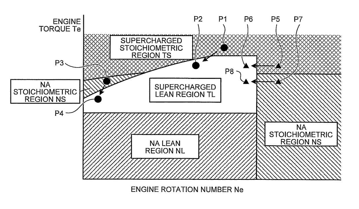
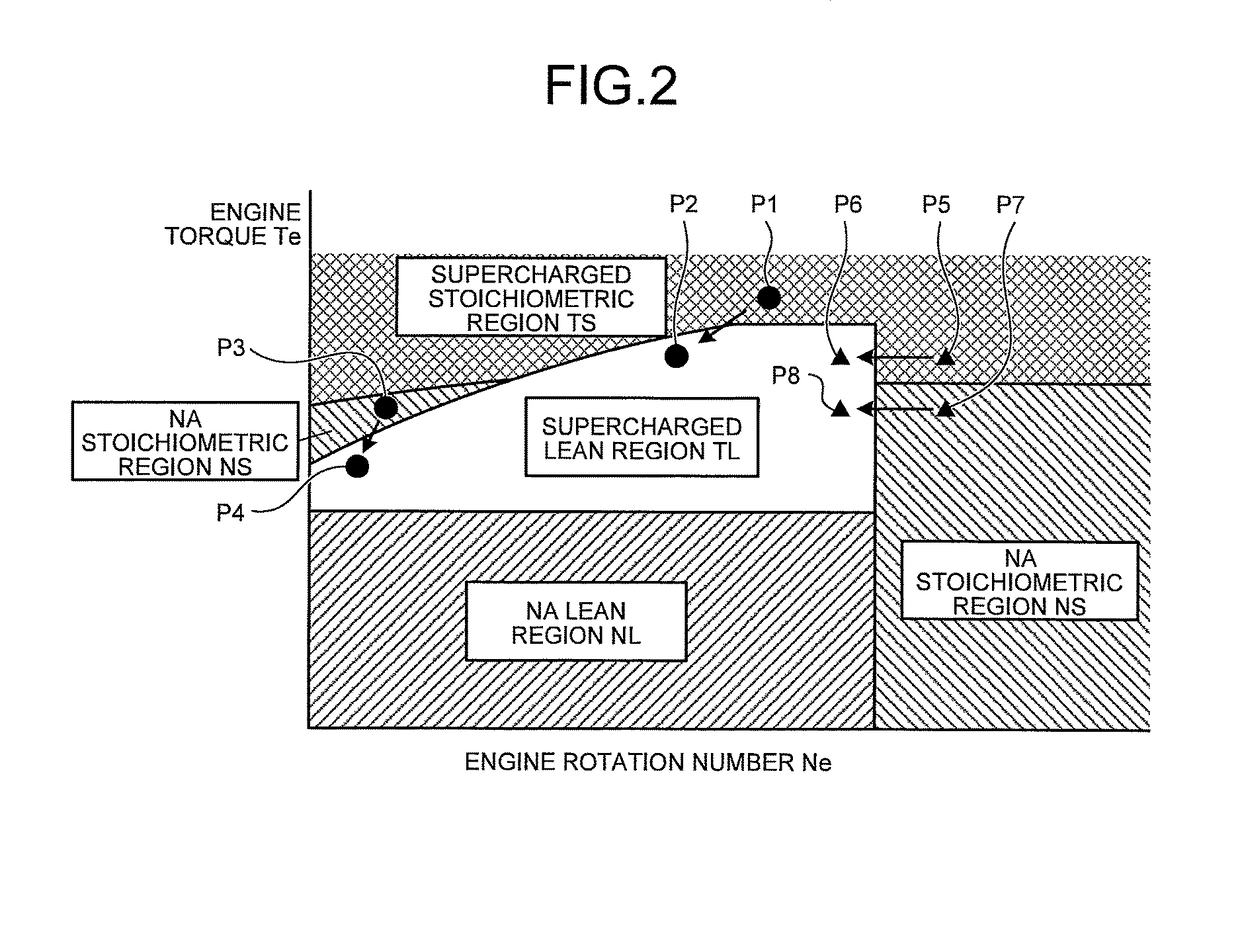
[0092]On the contrary, a vehicle control device according to the second embodiment regulates the execution of the up-shift when the up-shift condition is satisfied and the switching condition is satisfied (e.g., when the engine operation point is presumed to transition from an engine operation point P5 (FIG. 2) to an engine operation point P6 (FIG. 2)) under a situation the accelerator is constant and the ve...

third embodiment

[0113

[0114]A third embodiment of the present invention will now be described.

[0115]In the following description, the same reference numerals are denoted on the configurations and steps similar to the second embodiment described above, and the detailed description will be omitted or simplified.

[0116]In the second embodiment and the modification thereof described above, the combustion mode before switching to the supercharged lean combustion mode is the supercharged stoichiometric combustion mode or the NA stoichiometric combustion mode.

[0117]In the third embodiment, on the other hand, the combustion mode before switching to the supercharged lean combustion mode is the combustion mode (hereinafter referred to as rich spike combustion mode) of executing a rich spike control of purifying the nitrogen oxide occluded in a catalyst.

[0118]Configuration of Vehicle

[0119]FIG. 7 is a diagram schematically illustrating a configuration of a vehicle 1A according to a third embodiment of the presen...


PUM


Abstract

A vehicle control device includes: a change gear ratio changing circuit configured to execute an up-shift of a change gear ratio in an automatic transmission; a change gear ratio determination circuit configured to determine whether or not an up-shift condition is satisfied based on a change gear diagrammatic view; a combustion mode determination circuit configured to determine whether or not a switching condition for switching from a predetermined combustion mode, in which an air-fuel ratio of the engine is an air-fuel ratio on a rich side than a lean air-fuel ratio, to a supercharged lean combustion mode, in which the air-fuel ratio of an engine is made to the lean air-fuel ratio while executing supercharging by a supercharger, is satisfied; and a change regulating circuit configured to regulate the change gear ratio changing circuit to execute the up-shift at the time both conditions are satisfied.

Description

CROSS-REFERENCE TO RELATED APPLICATIONS[0001]The present application claims priority to and incorporates by reference the entire contents of Japanese Patent Application No. 2014-179409 filed in Japan on Sep. 3, 2014.BACKGROUND OF THE INVENTION[0002]1. Field of the Invention[0003]The present invention relates to a vehicle control device.[0004]2. Description of the Related Art[0005]A vehicle control device that is mounted on a vehicle, which includes an engine with a supercharger and an automatic transmission coupled to the engine, and that controls an air-fuel ratio of the engine according to an operation state of the engine to switch a combustion mode is conventionally known (see e.g., Japanese Patent Application Laid-Open No. 2009-144575 and Japanese Patent Application Laid-Open No. 2006-300253).[0006]Among the various combustion modes, a necessary intake air amount is large in a lean combustion mode (hereinafter described as a supercharged lean combustion mode), in which superchar...

Claims


Application Information

Patent Timeline
Patent Type & Authority Patents(United States)
IPC IPC(8): F16H61/02F16H59/74F02D29/02F02D41/02F02D41/30B60W10/00F02D41/00F16H59/32F02D41/10
CPCF16H61/0213B60W10/00F02D29/02F02D41/0007F02D41/023F16H59/32F16H59/74F02D41/3064Y02T10/144F02D41/10F02D2200/101F02D2200/602B60W10/06B60W10/11B60W30/1882F02D23/02F02D41/021B60W2520/10B60W2710/1005B60W2710/0638B60W2540/10B60W2710/0622B60Y2400/435Y02T10/12
Inventor NAGAI, TADAYUKIKONDO, MASAMI
Owner TOYOTA JIDOSHA KK
Why Eureka
Try Eureka