Systems and methods for a variable geometry turbine nozzle

a variable geometry and turbine nozzle technology, applied in the direction of machines/engines, mechanical equipment, radial flow pumps, etc., can solve the problems of increasing boost pressure, increasing aerodynamic flow loss, and increasing the angle of incidence of gas flowing across the turbine blade, so as to improve engine torque and/or power output density, boost intake air pressure, and boost the effect of air pressure and flow

Active Publication Date: 2018-02-13
FORD GLOBAL TECH LLC
View PDF7 Cites 9 Cited by
  • Summary
  • Abstract
  • Description
  • Claims
  • Application Information

AI Technical Summary

Benefits of technology

[0003]Engines may use a turbocharger to improve engine torque and / or power output density. A turbocharger may include a turbine disposed in line with the engine's exhaust stream, and coupled via a drive shaft to a compressor disposed in line with the engine's intake air passage. The exhaust-driven turbine may then supply energy, via the drive shaft, to the compressor to boost the intake air pressure. In this way, the exhaust-driven turbine supplies energy to the compressor to boost the pressure and flow of air into the engine. Therefore, increasing the rotational speed of the turbine may increase boost pressure. The desired amount of boost may vary over operation of the engine. For example, the desired boost may be greater during acceleration than during deceleration.
[0006]The inventors herein have recognized potential issues with the approach identified above. For example, the sliding vane(s) may intrude at a high flow area of the inlet passages. In this way, intrusion of leading edges of the sliding vanes may create sub-optimal angles of incidence for the incoming gas and thereby lead to increased aerodynamic flow loss. Moreover, the sliding vane traveling on the planar surface may slide a relatively large distance in the radial direction into the high flow area of the inlet passage, thereby leading to packaging challenges.
[0008]The inventors herein have recognized the above issues and developed an approach to at least partly address the above issues. As one example, an annular turbine nozzle may be provided, comprising a nozzle vane including a stationary vane attached to a surface of a nozzle wall plate and including a first sliding surface, and a sliding vane including a second sliding surface including a flow disrupting feature in contact with the first sliding surface, the sliding vane positioned to slide in a direction from substantially tangent to an inner circumference of the turbine nozzle and selectively uncovering the flow disrupting feature. In this way, the surface treatment may be exposed during various conditions, such as engine braking, to reduce the intensity of possible shock waves and excitation on the turbine blades.

Problems solved by technology

Therefore, increasing the rotational speed of the turbine may increase boost pressure.
Furthermore, the angle of incidence of gas flowing across the turbine blades may affect the efficiency of the turbine, e.g., the amount of thermodynamic energy captured from the flow that is converted to mechanical energy.
In this way, intrusion of leading edges of the sliding vanes may create sub-optimal angles of incidence for the incoming gas and thereby lead to increased aerodynamic flow loss.
Moreover, the sliding vane traveling on the planar surface may slide a relatively large distance in the radial direction into the high flow area of the inlet passage, thereby leading to packaging challenges.
Further, the above methods and systems do not address potential shock waves generated during certain engine operating conditions, such as engine braking.
During engine braking, the exhaust stream may be constricted, and therefore, shock waves may be generated, leading to strong interaction and excitation on the turbine blades.
The shock wave-induced excitation, also referred to as forced response excitation or fluid structure interaction, may be a source of fatigue on the turbine blades and a limiting factor of further increasing exhaust braking power of turbocharged engines.

Method used


Image

  • Systems and methods for a variable geometry turbine nozzle
  • Systems and methods for a variable geometry turbine nozzle
  • Systems and methods for a variable geometry turbine nozzle

Examples


Embodiment Construction

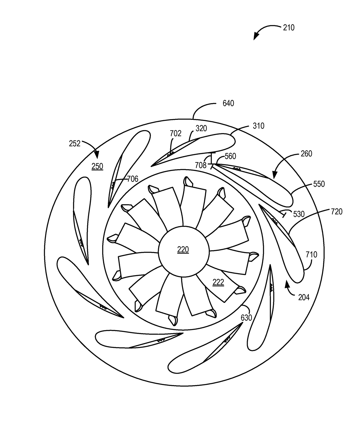
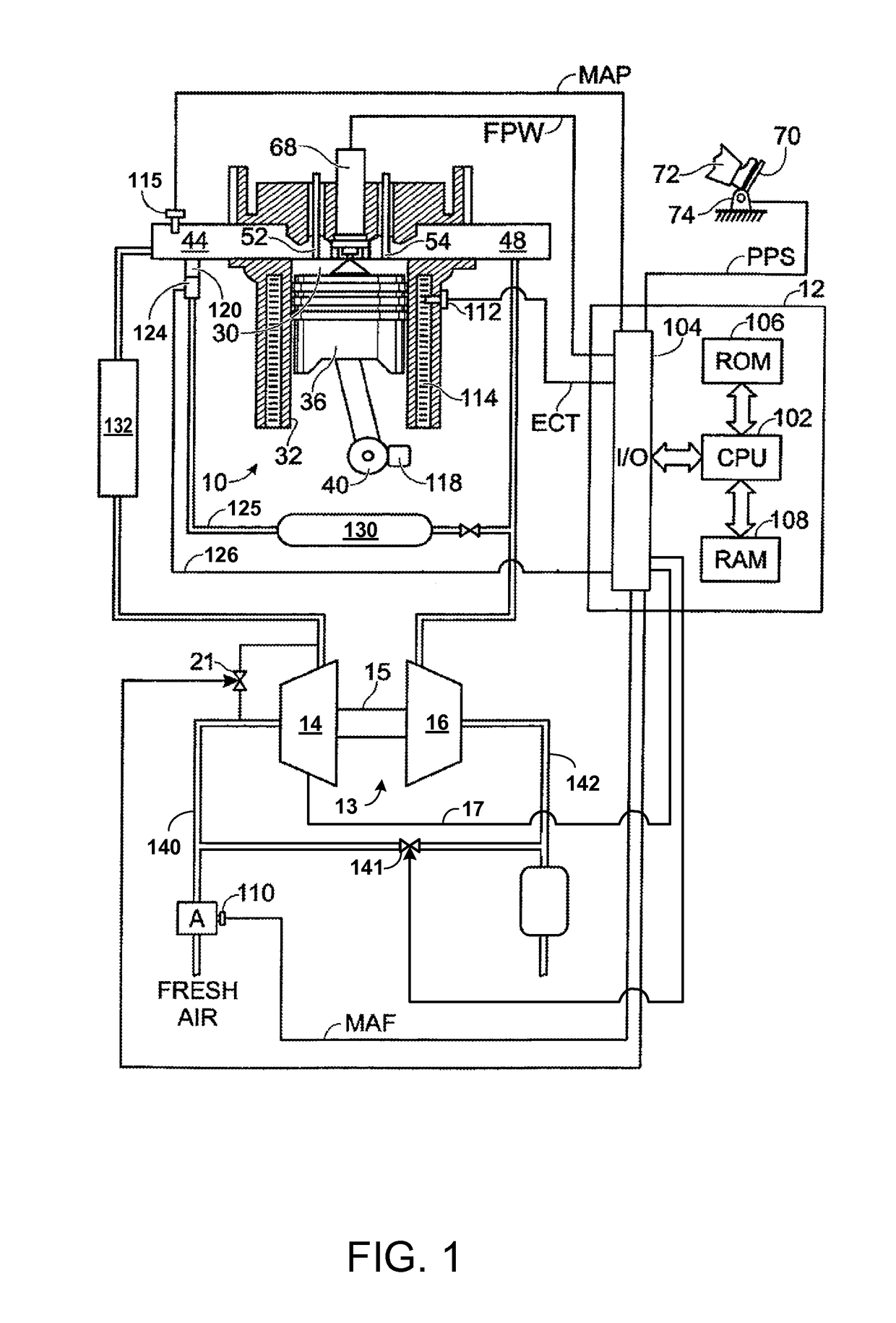
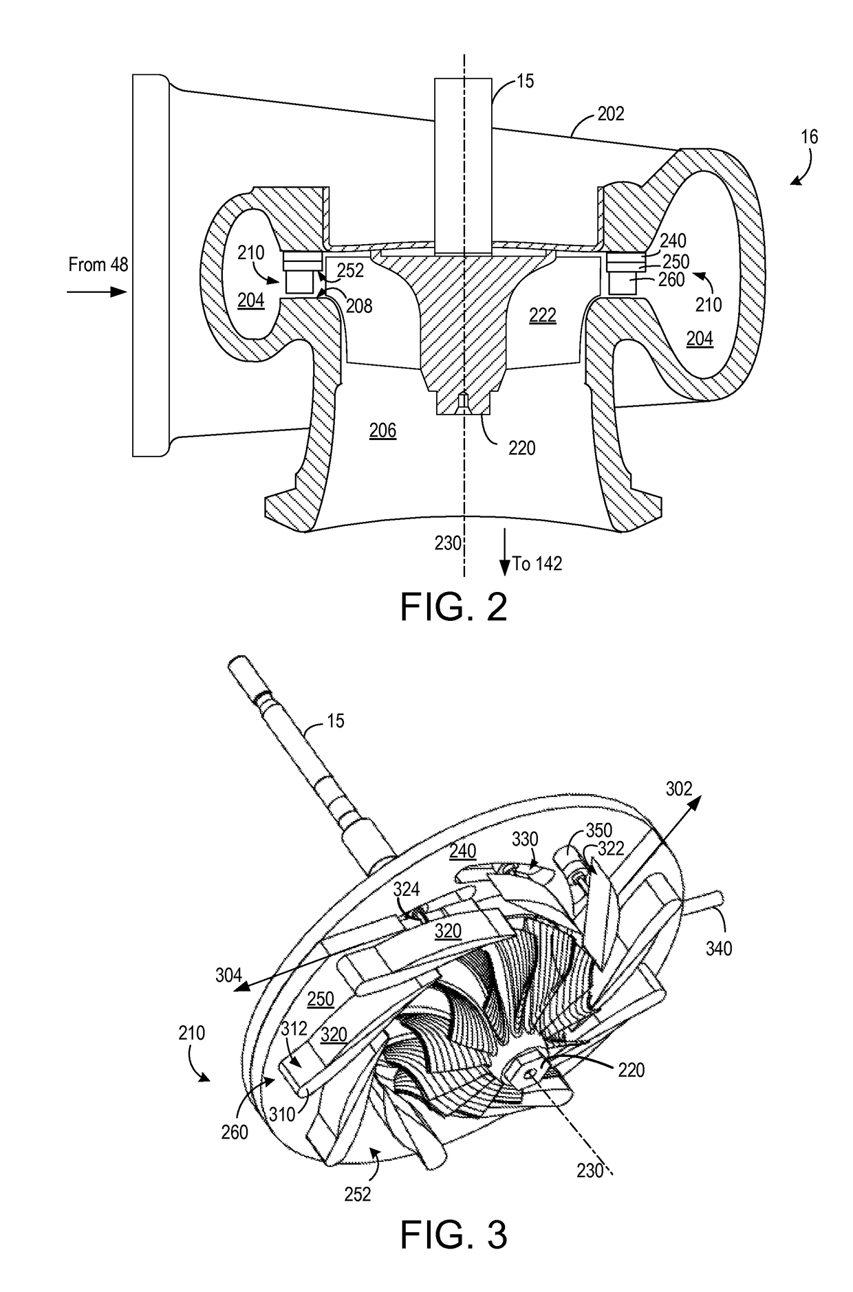
[0023]The following description relates to systems and methods for variable geometry turbochargers of internal combustion engines. An example engine with a turbocharger is illustrated in FIG. 1. The example turbocharger includes a compressor driven by a turbine, such as the turbine illustrated in FIG. 2. The turbine may include a turbine nozzle and a turbine wheel, such as shown in more detail in FIGS. 3-8. FIG. 3 shows a perspective view of an example embodiment of a turbine nozzle and a turbine wheel. Similarly, FIG. 4 shows a perspective view of an example embodiment of the turbine nozzle having nozzle vanes. In one example, each nozzle vane may include a stationary vane and a sliding vane having flat sliding surfaces, as shown on the top image of FIG. 5. In another example, each nozzle vane may include a stationary vane and a sliding vane having cambered (e.g., curved) sliding surfaces, as shown on the bottom image of FIG. 5. Further, the nozzle vane having a stationary vane and...


PUM


Abstract

Various systems and methods are described for a variable geometry turbine. In one example, a nozzle vane includes a stationary having a first cambered sliding surface and a sliding vane having a second cambered sliding surface where the second cambered sliding surface includes a flow disrupting feature in contact with the first sliding cambered surface. The sliding vane may be positioned to slide in a direction from substantially tangent along a curved path to an inner circumference of the turbine nozzle and selectively uncover the flow disrupting feature.

Description

CROSS REFERENCE TO RELATED APPLICATIONS[0001]The present application claims priority to U.S. Provisional Patent Application No. 62 / 082,899, “SYSTEMS AND METHODS FOR A VARIABLE GEOMETRY TURBINE NOZZLE,” filed on Nov. 21, 2014, the entire contents of which are hereby incorporated by reference for all purposes.FIELD[0002]The present application relates to variable geometry turbines for turbochargers of internal combustion engines.BACKGROUND AND SUMMARY[0003]Engines may use a turbocharger to improve engine torque and / or power output density. A turbocharger may include a turbine disposed in line with the engine's exhaust stream, and coupled via a drive shaft to a compressor disposed in line with the engine's intake air passage. The exhaust-driven turbine may then supply energy, via the drive shaft, to the compressor to boost the intake air pressure. In this way, the exhaust-driven turbine supplies energy to the compressor to boost the pressure and flow of air into the engine. Therefore, ...

Claims


Application Information

Patent Timeline
Patent Type & Authority Patents(United States)
IPC IPC(8): F04D17/14F02B37/24F02B39/00F01D17/16F01D5/14
CPCF02B37/24F01D17/165F02B39/00Y02T10/144F05D2210/30F05D2220/40F05D2240/12F01D5/141Y02T10/12
Inventor SUN, HAROLD HUIMINZHAO, BENHU, LEONYI, JIANWEN JAMESCURTIS, ERIC WARRENZHANG, JIZHONG
Owner FORD GLOBAL TECH LLC
Why Eureka
Try Eureka