[0010] Although the
conventional technique disclosed in the
Patent Literature 2 does not have the
disadvantage when the microcomputer program is used, the following
disadvantage occurs. Since the
time constant circuit is provided in the video amplification circuit, it is necessary to prepare a dedicated wire for connecting substrates so as to carry a current to the
time constant circuit. The disadvantage of the invention disclosed in the Patent Literature 2 will be described in more detail with reference to the drawings.
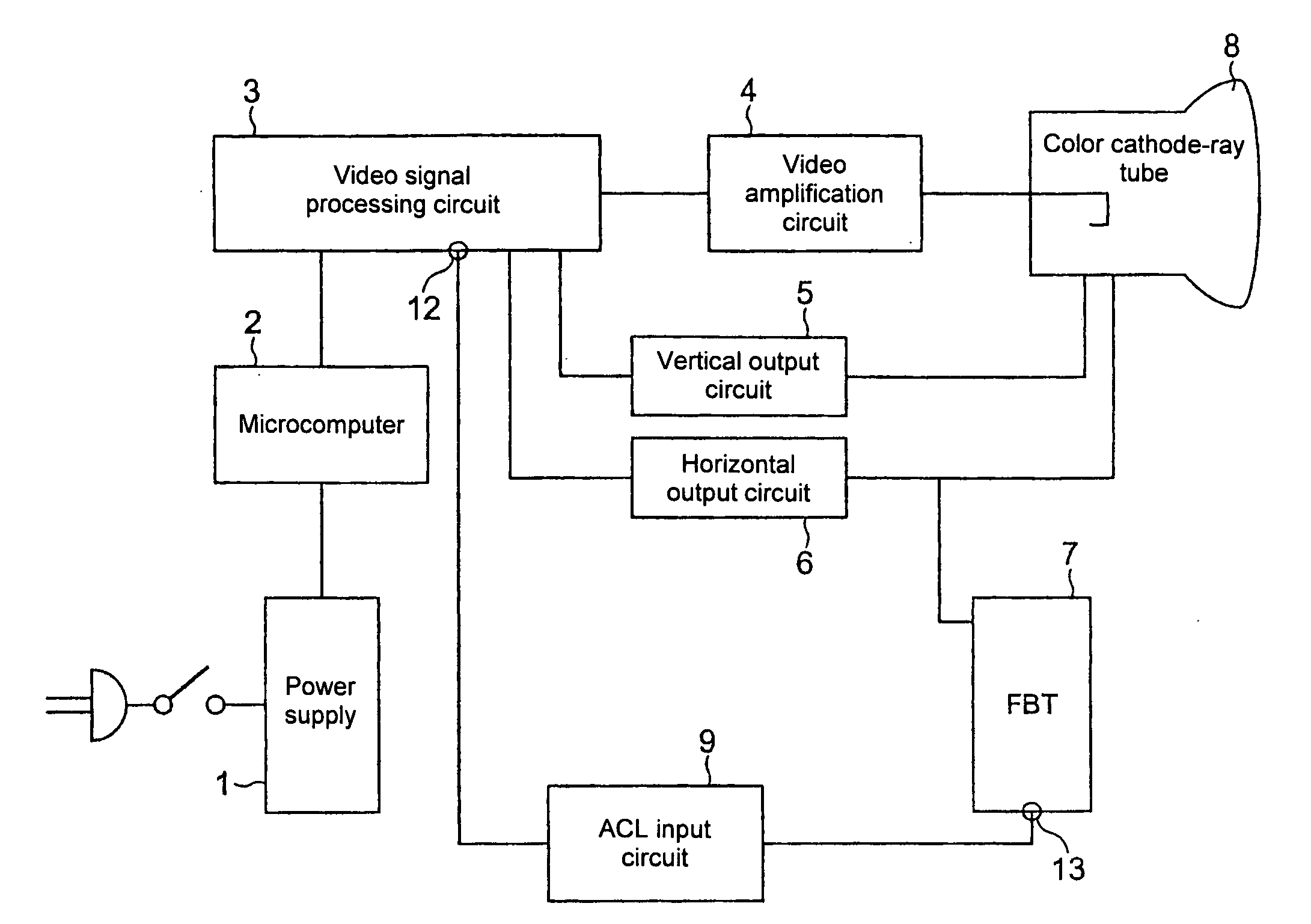
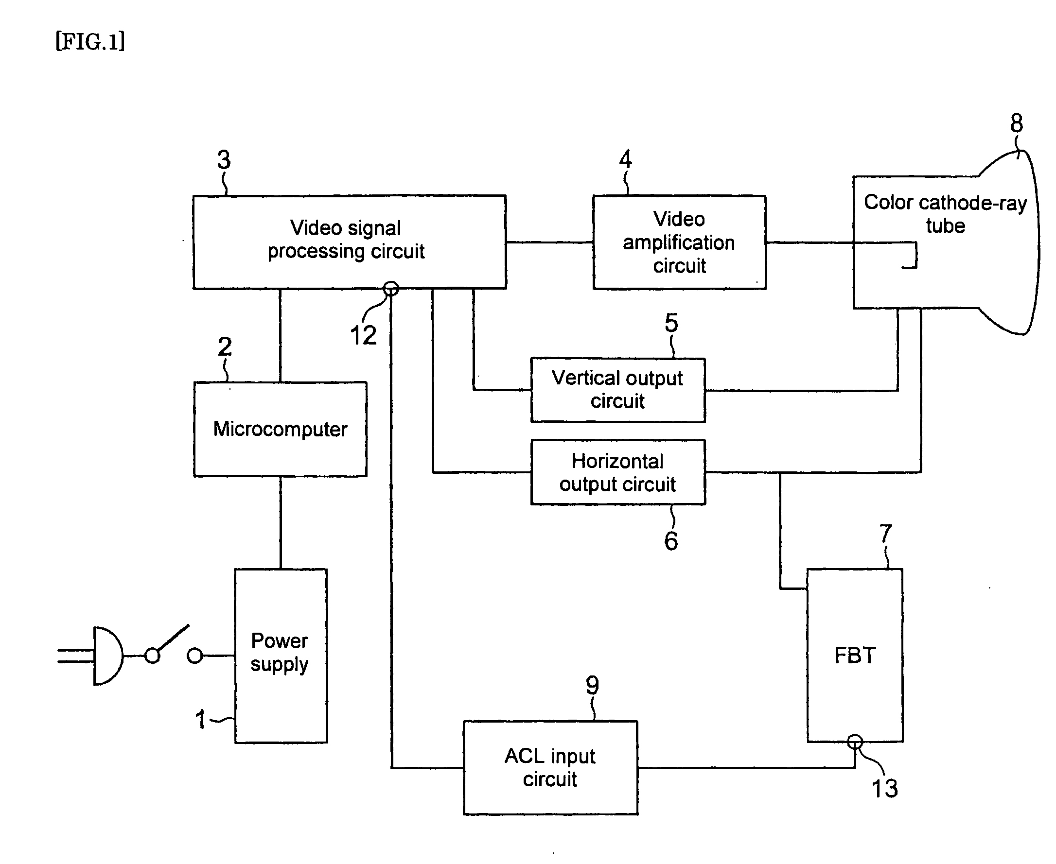
[0011]FIG. 1 is a
block diagram which depicts an ordinary
video output circuit of a color television receiver. The
video output circuit is composed by a power supply 1, a microcomputer 2, a video
signal processing circuit 3, a video amplification circuit 4, a vertical output circuit 5, a horizontal output circuit 6, a
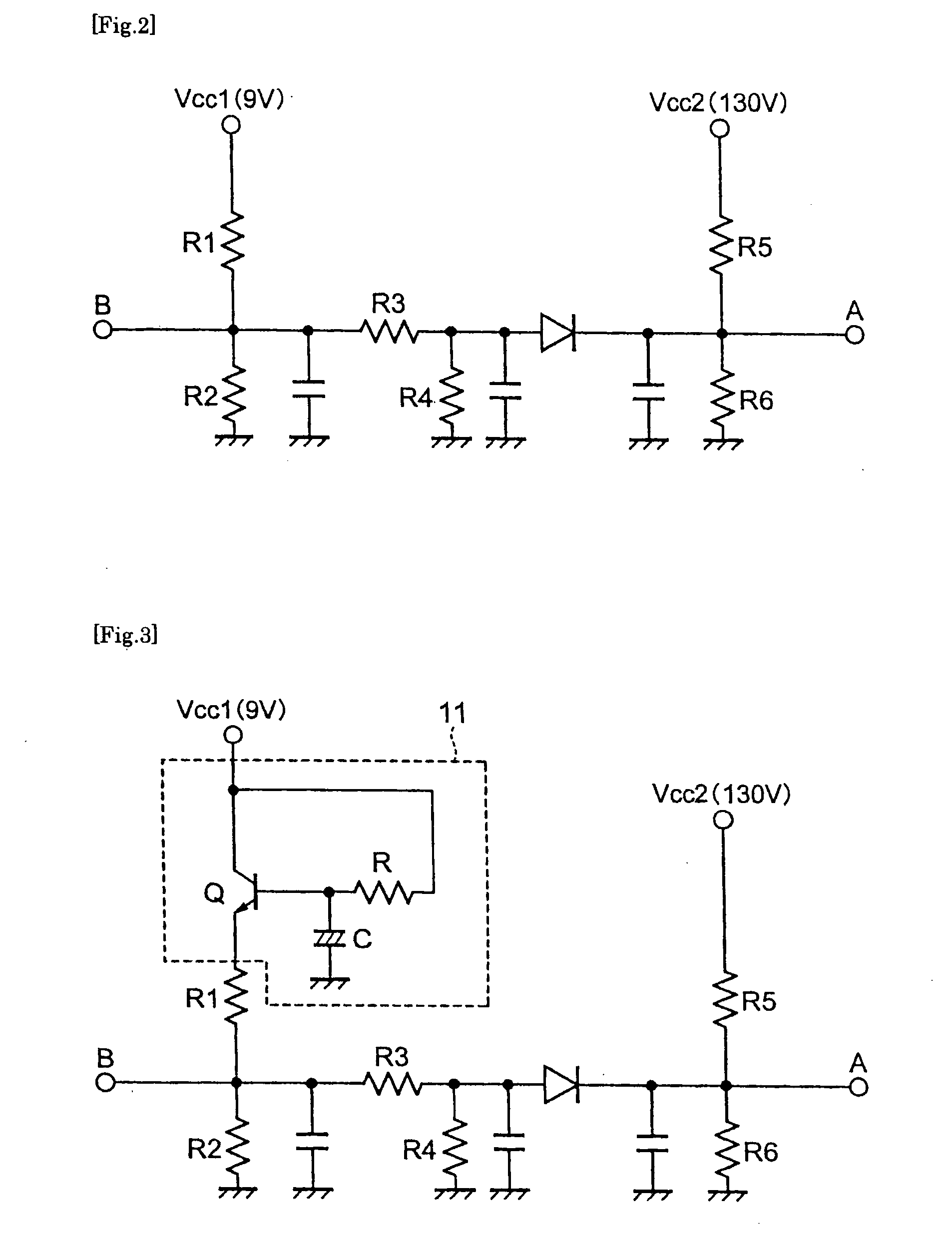
flyback transformer (“FBT”) 7, a color CRT 8, and an auto-contrast limiter (“ACL”) input circuit 9. FIG. 2 depicts one example of a
circuit diagram of a conventional ACL input circuit. A point A is connected to an auto-brightness limiter (“
ABL”) terminal 13 of the FBT 7. A
voltage according to a beam current carried to the color CRT is detected by detection resistors R5 and R6. When the beam current carried to the color CRT is increased, that is, a picture displayed on a display screen is a bright picture, the
voltage at the point A is reduced. When the beam current carried to the color CRT is reduced, that is, the picture displayed on the display screen is a dark picture, the
voltage at the point A is increased. A voltage at a point B obtained after the detected voltage is adjusted by resistors R1, R2, R3, and R4 is input to an ACL input terminal 12 of the video
signal processing circuit 3. The video
signal processing circuit 3 controls a contrast of the video signal according to the voltage input from the ACL input terminal 12. Namely, the video
signal processing circuit 3 includes an ACL circuit that controls the contrast of the video signal to be reduced when the beam current carried to the color CRT 8 is increased, thereby limiting the beam current carried to the color CRT 8. As for an
integrated circuit (IC) for the video signal
processing, not only the video signal
processing IC including the ACL input terminal as described above but also a video signal processing circuit IC including an
ABL input terminal and a video signal processing circuit IC including an auto
brightness contrast limiter (“ABCL”) input terminal have been put to practical use. Using such an IC including the
ABL input terminal or the ABCL input terminal, an ABL circuit or an ABCL circuit is constituted. The ABL circuit controls a brightness of the video signal and the ABCL circuit controls both the brightness and the contrast of the video signal, thereby controlling the beam current carried to the color CRT.
[0012] The invention disclosed in the Patent Literature 2 is intended to
delay rising of a voltage to be applied to the cathode of the color CRT 8 and thereby prevent occurrence of smearing right after the television receiver is turned on by providing the time constant circuit composed by the
resistor, the
capacitor, and the
transistor in the video amplification circuit 4 in FIG. 1. FIG. 4 is a
circuit diagram of the video amplification circuit including the time constant circuit according to the Patent Literature 2 (referred to as “power-ON time smearing
elimination circuit” in the Patent Literature 2). While only the time constant circuit for B is shown in FIG. 4, time constant circuits for R and G, not shown, are similarly necessary. In addition, a cable that is a dedicated wire for supplying a voltage of 12 volts to be applied to these time constant circuits is necessary. SUMMARY OF THE INVENTION
[0013] The present invention has been achieved to solve the conventional disadvantages. It is an object of the present invention to provide a limiter circuit for a color television receiver capable of dispensing with a wire for carrying a current as required in the Patent Literature 2, capable of solving the disadvantage of the Patent Literature 1 that a contrast is reduced on a display screen if a user temporarily turns off the receiver for some reason and turns on the receiver again right after turning off the receiver, and capable of preventing occurrence of smearing right after the receiver is turned on when the user views a program using the color television receiver, and to provide the color television receiver including the limiter circuit.
[0014] According to a first aspect of the present invention, there are provided a limiter circuit, for limiting a beam current carried to a color cathode-ray tube by detecting the beam current carried to the color cathode-ray tube, and controlling a level of at least one of a contrast and a brightness of a video signal, wherein a time constant circuit composed by a
resistor, a
capacitor, and a
transistor is provided on a power supply line for supplying a power to the limiter circuit, so as to
delay supply of the power to the limiter circuit, thereby preventing occurrence of smearing on a display screen right after the power is turned on, and a television receiver including the limiter circuit. According to a second aspect of the present invention, there is provided a television receiver using a color cathode-ray tube, comprising: an auto-contrast limiter circuit or ACL circuit, an auto-brightness limiter circuit or ABL circuit, or an auto
brightness contrast limiter circuit or ABCL circuit constituted so that a voltage detected at an ABL terminal of a
flyback transformer or FBT is input to an ACL input terminal, an ABL input terminal, or an ABCL input terminal of a video signal processing
integrated circuit or video signal processing IC, wherein a time constant circuit composed by a
resistor, a
capacitor, and a
transistor is provided on a power supply line for supplying a power to an input level adjustment resistor, which resistor adjusts an input level of the power input to the ACL input terminal, the ABL input terminal, or the ABCL input terminal of the video signal processing IC so as to reduce the voltage input to the ACL input terminal, the ABL input terminal, or the ABCL input terminal of the video signal processing IC right after the television receiver is turned on, thereby preventing occurrence of smearing on the display screen right after the television receiver is turned on.
[0015] According to the present invention, the limiter circuit that limits the beam current carried to the color cathode-ray tube and that is constituted so that the time constant circuit composed by the resistor, the capacitor, and the transistor is provided on a power supply line for supplying a power to the limiter circuit, so as to delay supply of the power to the limiter circuit, thereby preventing occurrence of smearing on a display screen right after the color television receiver is turned on is provided. It is thereby possible to dispense with a dedicated wire for connecting substrates for carrying a current, and to prevent occurrence of the smearing on the display screen right after the television receiver is turned on if the user temporarily turns off the receiver for some reason and turns on the receiver again right after turning off the receiver.

