
Network system and method for automatically interfacing with communication apparatus of different standard

a communication apparatus and network control technology, applied in the field of communication apparatus, can solve the problems of direct current flowing through the network control section of the communication apparatus, different from those of the conventional standard, and the inability to form a network connection between the communication apparatus and the internal line exchanger

Inactive Publication Date: 2006-12-05
RICOH KK
View PDF12 Cites 4 Cited by
  • Summary
  • Abstract
  • Description
  • Claims
  • Application Information

AI Technical Summary

Benefits of technology

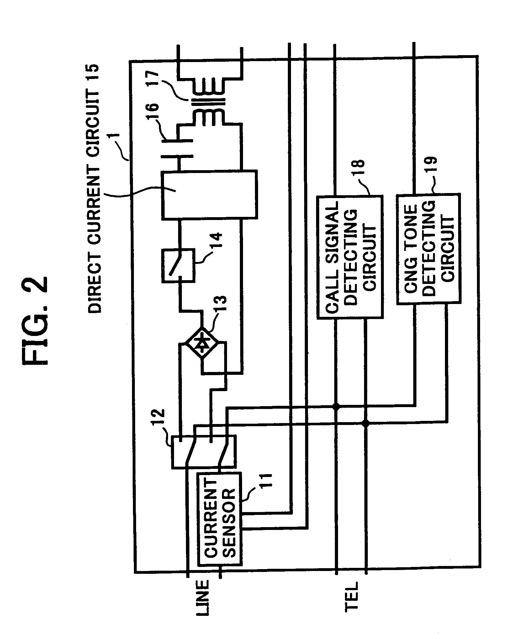
[0053]The network control section 1 may include the following devices illustrated in FIG. 2. A relay 12 capable of connecting to the line 3 through a connection that corresponds to a telephone mode (hereinafter referred to as a “TEL” mode) or a facsimile mode, a current sensor 11 that detects a current flowing through the line 3, and a CNG tone detecting circuit 19 for detecting a tone signal, such as CNG, that indicates that a communication transmitter is a facsimile apparatus, may be provided. A call signal detecting circuit 18 for detecting a ringing signal and binalizing its ringing wave, and a diode bridge 13 for adjusting a polarity of the direct current voltage may be provided.
[0052]Further, a power source voltage may be supplied to each unit of the facsimile when the principal control section 21 transmits a power source control signal to a power source switching section (not shown). Furthermore, each section may perform any necessary data communication via a bus line.
[0030]In yet another embodiment, a parameter generating device may be provided to generate a parameter representing a limit on the direct current, and the parameter need not be generated and included in parameters related to the control of the network when communication is practiced via a network other than a general public line.
[0053]The network control section 1 may include the following devices illustrated in FIG. 2. A relay 12 capable of connecting to the line 3 through a connection that corresponds to a telephone mode (hereinafter referred to as a “TEL” mode) or a facsimile mode, a current sensor 11 that detects a current flowing through the line 3, and a CNG tone detecting circuit 19 for detecting a tone signal, such as CNG, that indicates that a communication transmitter is a facsimile apparatus, may be provided. A call signal detecting circuit 18 for detecting a ringing signal and binalizing its ringing wave, and a diode bridge 13 for adjusting a polarity of the direct current voltage may be provided.
[0031]In yet another embodiment, the parameter is set using the setting switch or a screen provided in the communication apparatus.
[0030]In yet another embodiment, a parameter generating device may be provided to generate a parameter representing a limit on the direct current, and the parameter need not be generated and included in parameters related to the control of the network when communication is practiced via a network other than a general public line.
[0030]In yet another embodiment, a parameter generating device may be provided to generate a parameter representing a limit on the direct current, and the parameter need not be generated and included in parameters related to the control of the network when communication is practiced via a network other than a general public line.
[0030]In yet another embodiment, a parameter generating device may be provided to generate a parameter representing a limit on the direct current, and the parameter need not be generated and included in parameters related to the control of the network when communication is practiced via a network other than a general public line.
[0030]In yet another embodiment, a parameter generating device may be provided to generate a parameter representing a limit on the direct current, and the parameter need not be generated and included in parameters related to the control of the network when communication is practiced via a network other than a general public line.
[0030]In yet another embodiment, a parameter generating device may be provided to generate a parameter representing a limit on the direct current, and the parameter need not be generated and included in parameters related to the control of the network when communication is practiced via a network other than a general public line.

Problems solved by technology

However, the characteristics of a direct current that flows through a network control section of a communication apparatus, e.g., a facsimile, are different from those of the conventional standard.
Further, since communication standards adopted by many countries (excepting Europe) are not uniform, linear characteristics are required in several countries, and the direct current characteristics must be changed to those of a destination country.
When using such an internal line exchanger, it has been shown that it is impossible to form a network connection between a communication apparatus and an internal line exchanger if the communication apparatus operates at a current value in excess of the prescribed limit upon the direct current.
Thus, the above-mentioned current limitation is generally not applied in internal line exchangers.
However, the above-mentioned related technology can not generate a direct current that includes nonlinear characteristics that limit a current flowing through the circuit to a prescribed value.
This is thus a source of problems.

Method used


Image

  • Network system and method for automatically interfacing with communication apparatus of different standard
  • Network system and method for automatically interfacing with communication apparatus of different standard
  • Network system and method for automatically interfacing with communication apparatus of different standard

Examples


first embodiment

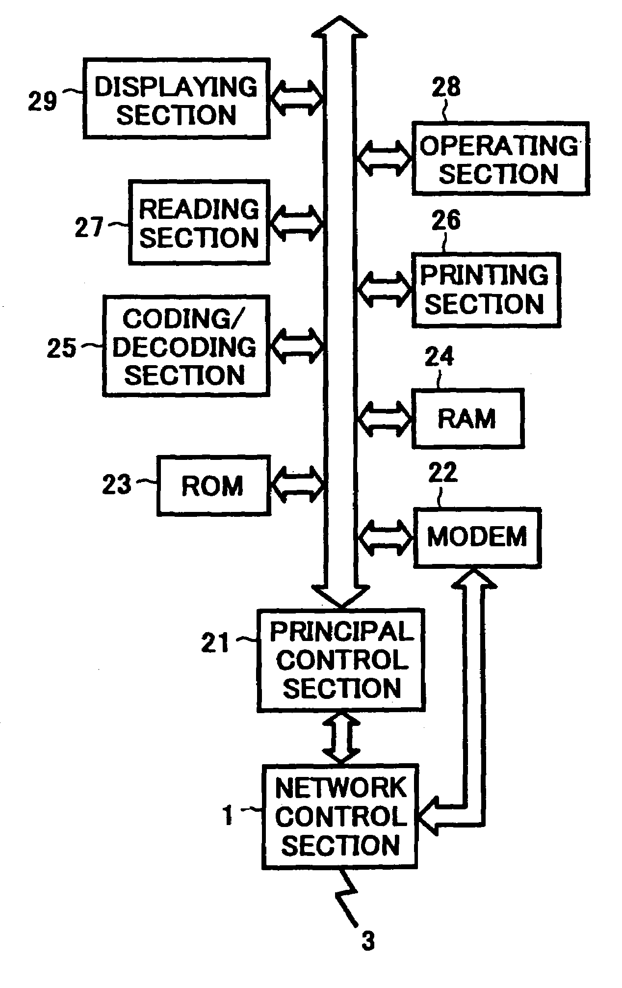
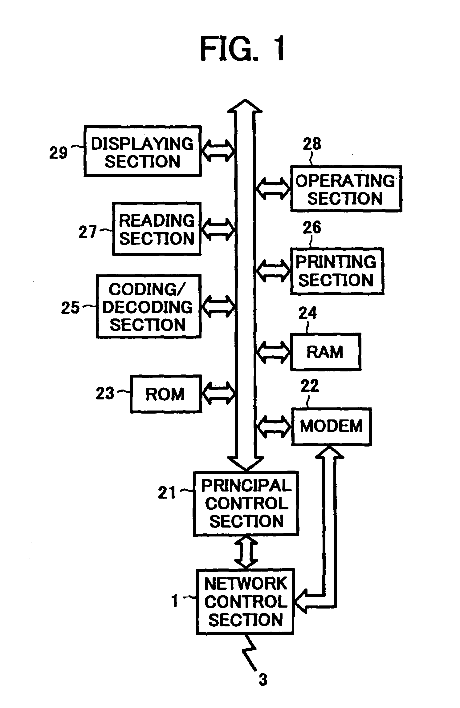
[0044]The first embodiment is now described referring to FIGS. 1, 2 and 3. A principal control section 21 may include a central processing unit (hereinafter referred to as a CPU) or similar device and perform processing operations of internal sections and its elements of the facsimile apparatus according to a variety of control programs stored in a ROM 23.

[0045]A RAM 24 may store a variety of data and include a work area for use in the control of the facsimile apparatus. The RAM 24 may store a predetermined dial number, such as zero, used when switching from an internal line to an external line, a predetermined dial number used when switching to an internal line from an external line, a frequency of a ringing wave of an internal and / or external line, and / or a cadence ON / OFF time period representing signal ON / OFF timing or the like. Furthermore, the RAM 24 may double as an image memory for storing image data encoded by an encoding / decoding section 25. The encoding / decoding section 25...

third embodiment

[0090] since the switching device 151 may automatically operate according to a communication standard of the country to which the communication is transmitted or from which the communication is received, when a prescribed country is designated, the direct current characteristics can properly and automatically be attained using a facile operation.

[0091]The fourth embodiment is now described referring to FIGS. 9 and 10. A construction of a network control section 1 having a direct current circuit 15 is substantially the same as in the second embodiment. The network control sectional may include a photo-coupler and a transducer or the like. The network control section 1 may include a call signal detection circuit 19 or the like. When call is generated, the principal control section 21 may determine from a dial pulse or a dial number of a DTMF signal or a PB signal transmitted from the network control section 1, whether it is communication to be practiced by the general public line netw...


PUM


Abstract

A communication apparatus including a network control unit for interfacing with a telephone line. The network control unit comprises a direct current circuit in which a loop state direct current can flow, and a direct current limiting device for limiting the loop state direct current to a prescribed value when communication with a foreign country that has adopted a different communication standard is performed.

Description

CROSS-REFERRENCE TO RELATED APPLICATIONS[0001]This application is a Rule 1.53(b) continuation, and claims the priority, of U.S. Ser. No. 09 / 675,100, filed Sep. 28, 2000 now U.S. Pat. No. 6,754,319, the entire contents of which is herein incorporated by reference.[0002]This application claims priority of Japanese Patent Application Nos. 11-278611 filed on Sep. 30, 1999 and 2000-066984 filed on Mar. 10, 2000, the entire contents of which are hereby incorporated herein by reference.BACKGROUND OF THE INVENTION[0003]1. Field of the Invention[0004]The present invention generally relates to a communication apparatus, and in particular relates to a telephone line interface between a facsimile and a copier, a printer, and / or a card MODEM or the like that has a facsimile function.[0005]2. Discussion of the Background Art[0006]Recently, communication standards adopted by European countries have been unified into the Common Technical Regulation 21 (hereinafter referred to as the CTR 21).[0007]H...

Claims


Application Information

Patent Timeline
Patent Type & Authority Patents(United States)
IPC IPC(8): H04M11/00H04M19/08H04N1/32H04N1/327H04Q1/30
CPCH04N1/32704H04N1/3273H04N1/33361H04Q1/30
Inventor ORIKASA, NORIAKIOKABE, SHOUZI
Owner RICOH KK
Learn More