

Power conversion circuit, inverter and method for driving inverter
- Summary
- Abstract
- Description
- Claims
- Application Information
AI Technical Summary
Benefits of technology
Problems solved by technology
Method used
Image

Examples
Embodiment Construction
[0035]Hereinafter, embodiments disclosed herein will be described in detail with reference to the accompanying drawings, and the same or similar components are denoted by the same reference numerals and redundant description thereof will be omitted. In describing the present invention, if a detailed explanation for a related known function or construction is considered to unnecessarily divert the gist of the present disclosure, such explanation has been omitted but would be understood by those skilled in the art.
[0036]The accompanying drawings are used to help easily understand the technical idea of the present disclosure and it should be understood that the idea of the present disclosure is not limited by the accompanying drawings. The idea of the present disclosure should be construed to extend to any alterations, equivalents and substitutes besides the accompanying drawings.
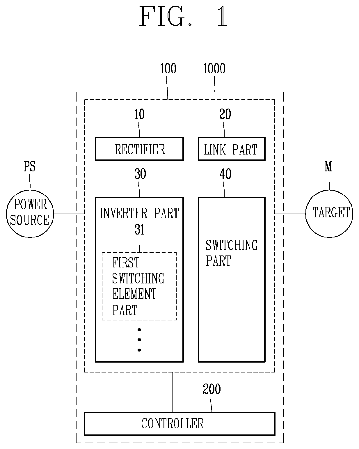
[0037]First, a power conversion circuit (hereinafter, referred to as a conversion circuit) according to the...
PUM
 Abstract
Description
Claims
Application Information