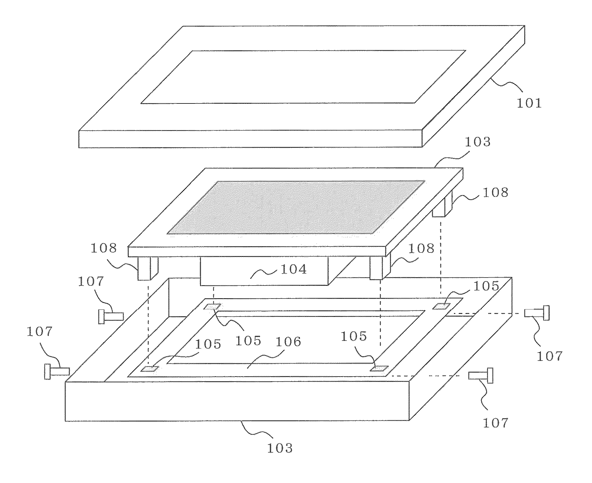
Coordinate input display apparatus
a display apparatus and input technology, applied in the field of coordinate input display apparatus, can solve the problems of inability to accurately obtain the pressed position, poor viewing experience, and restricted optical transmission, and achieve the effect of improving the detection accuracy of the pressed position
- Summary
- Abstract
- Description
- Claims
- Application Information
AI Technical Summary
Benefits of technology
Problems solved by technology
Method used
Image
Examples
embodiment 1
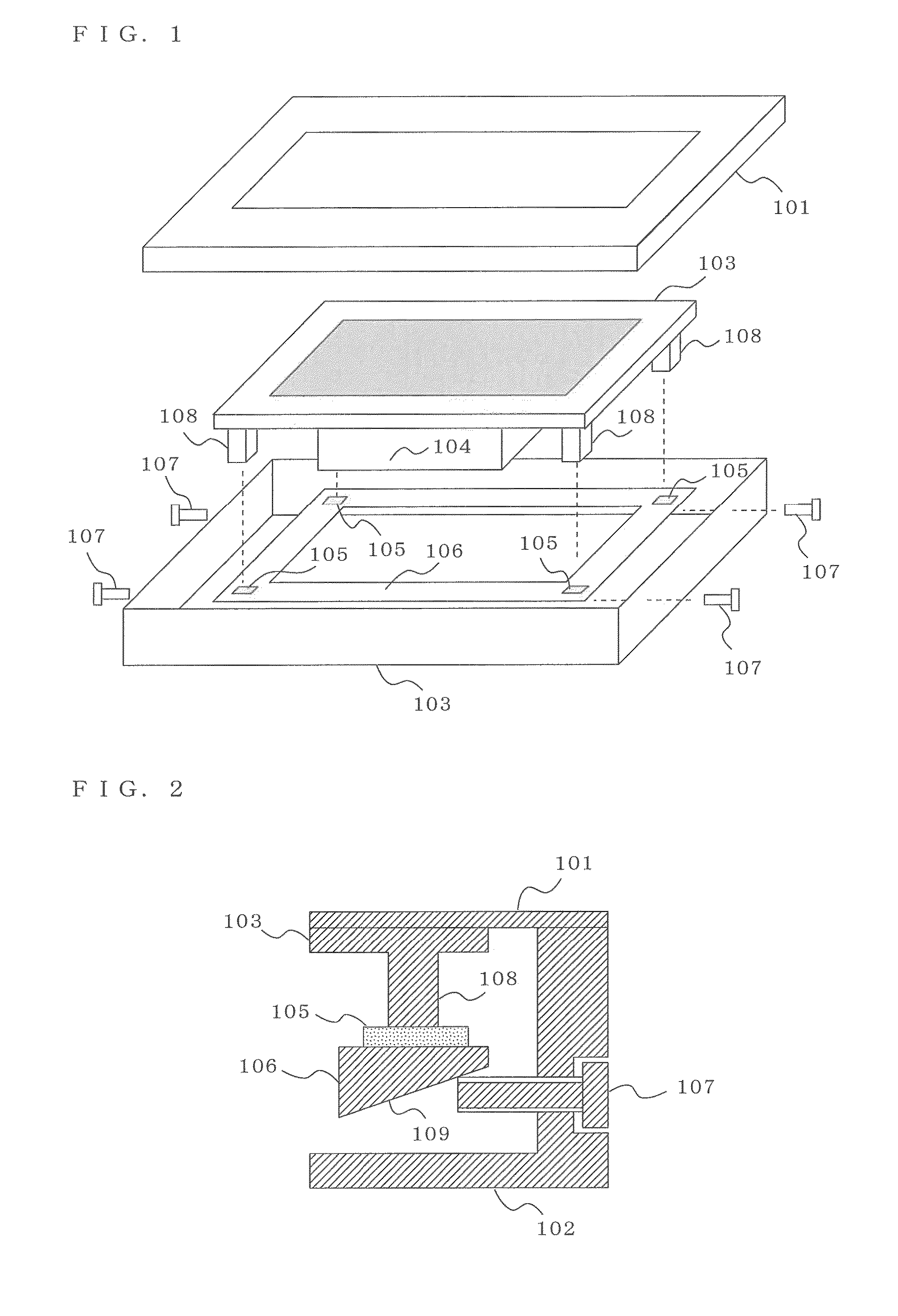
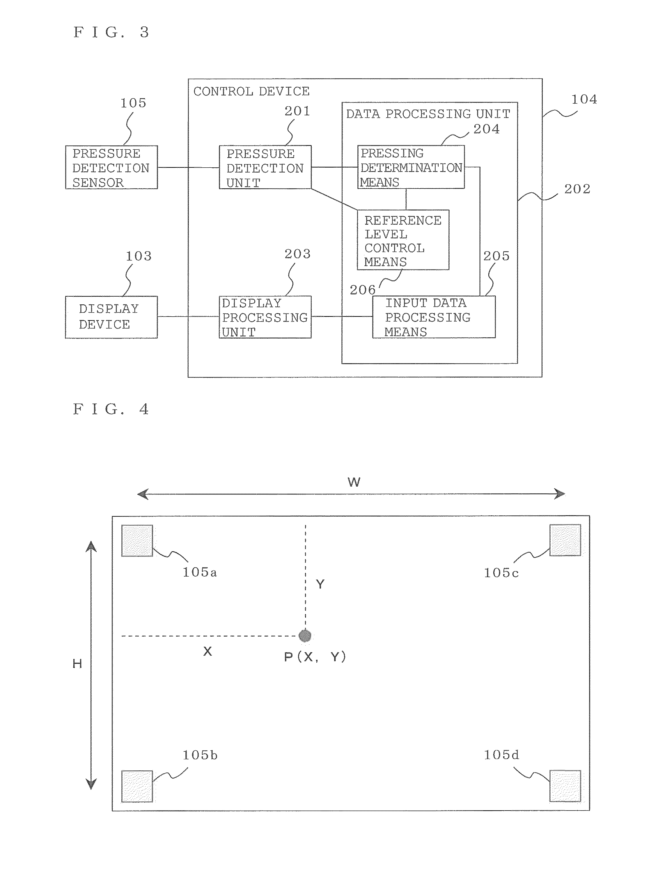
[0027]FIG. 1 is a structural view illustrating an example of a configuration of a coordinate input display apparatus according to Embodiment 1 of the present invention. As shown in FIG. 1, a coordinate input display apparatus according to Embodiment 1 includes a front side frame 101, a back side frame 102, a display device 103, a control device 104, a pressure detection sensor 105, a pressure detection panel 106, and an adjusting screw 107. The pressure detection panel 106 includes a sensor support member of the present invention.
[0028]The front side frame 101 and the back side frame 102 are each a frame forming the housing of the present coordinate input display apparatus. The display device 103 displays a screen by using a liquid-crystal display device, an organic EL display device, or the like. Furthermore, the display device 103 includes a pressing force transmission unit 108 in a projecting form and is in contact with the pressure detection sensor 105 by way of the pressing for...
embodiment 2
[0062]FIG. 10 is a structural view illustrating an example of a configuration of a coordinate input display apparatus according to Embodiment 2 of the present invention.
[0063]As shown in FIG. 2, the coordinate input display apparatus according to Embodiment 2 includes the front side frame 101, the back side frame 102, the display device 103, the control device 104, the pressure detection sensor 105, the pressure detection panel 106, and the reference level setting button 111.
[0064]The front side frame 101 and the back side frame 102 are each a frame forming the housing of the present coordinate input display apparatus. The display device 103 displays a screen by using a liquid-crystal display device, an organic EL display device, or the like. Furthermore, the display device 103 has a pressing force transmission unit 108 in a projecting form, and is in contact with the pressure detection sensor 105 by way of the pressing force transmission unit 108. The control device 104 controls th...
embodiment 3
[0082]FIG. 12 is a structural view illustrating an example of the configuration of a coordinate input display apparatus in Embodiment 3 of the present invention. As shown in FIG. 12, the coordinate input display apparatus according to Embodiment 3 includes the front side frame 101, the back side frame 102, the display device 103, the control device 104, the pressure detection sensor 105, and the pressure detection panel 106, with an operation button 112 being provided in the front side frame 101.
[0083]The front side frame 101 and the back side frame 102 are each a frame forming the housing of the present coordinate input display apparatus, and the front side frame 101 further includes the operation button 112. Furthermore, the front side frame 101 has the pressing force transmission unit 108 in a projecting form, and is in contact with the pressure detection sensor 105 by way of the pressing force transmission unit 108. The display device 103 displays a screen by using a liquid-crys...
PUM
 Abstract
Description
Claims
Application Information
 - R&D
- Intellectual Property
- Life Sciences
- Materials
- Tech Scout
- Unparalleled Data Quality
- Higher Quality Content
- 60% Fewer Hallucinations
Browse by: Latest US Patents, China's latest patents, Technical Efficacy Thesaurus, Application Domain, Technology Topic, Popular Technical Reports.
© 2025 PatSnap. All rights reserved.Legal|Privacy policy|Modern Slavery Act Transparency Statement|Sitemap|About US| Contact US: help@patsnap.com


