Wiping bar quick clamp

a technology of quick clamping and wiping bars, which is applied in the field of quick clamping of wiping bars, can solve the problems of difficult installation and/or re-installation of prior art wiping bars in the field, difficult time-consuming and laborious, and reduce the service life of the wiping bar assembly

Active Publication Date: 2014-07-22
L B FOSTER RAIL TECH INC
View PDF64 Cites 14 Cited by
  • Summary
  • Abstract
  • Description
  • Claims
  • Application Information

AI Technical Summary

Problems solved by technology

However, the problems associated with such clamping means, among other things, is that the prior art wiping bars are often difficult to install and / or re-install in the field whenever maintenance is performed on the rail or on the wiping bar itself.
In most prior art clamps of this type, the tightening and / or unloosening process is relatively slow and tedious, thus making installation and removal of the wiping bar assembly W1 difficult and time consuming.

Method used


Image

  • Wiping bar quick clamp
  • Wiping bar quick clamp
  • Wiping bar quick clamp

Examples


second embodiment

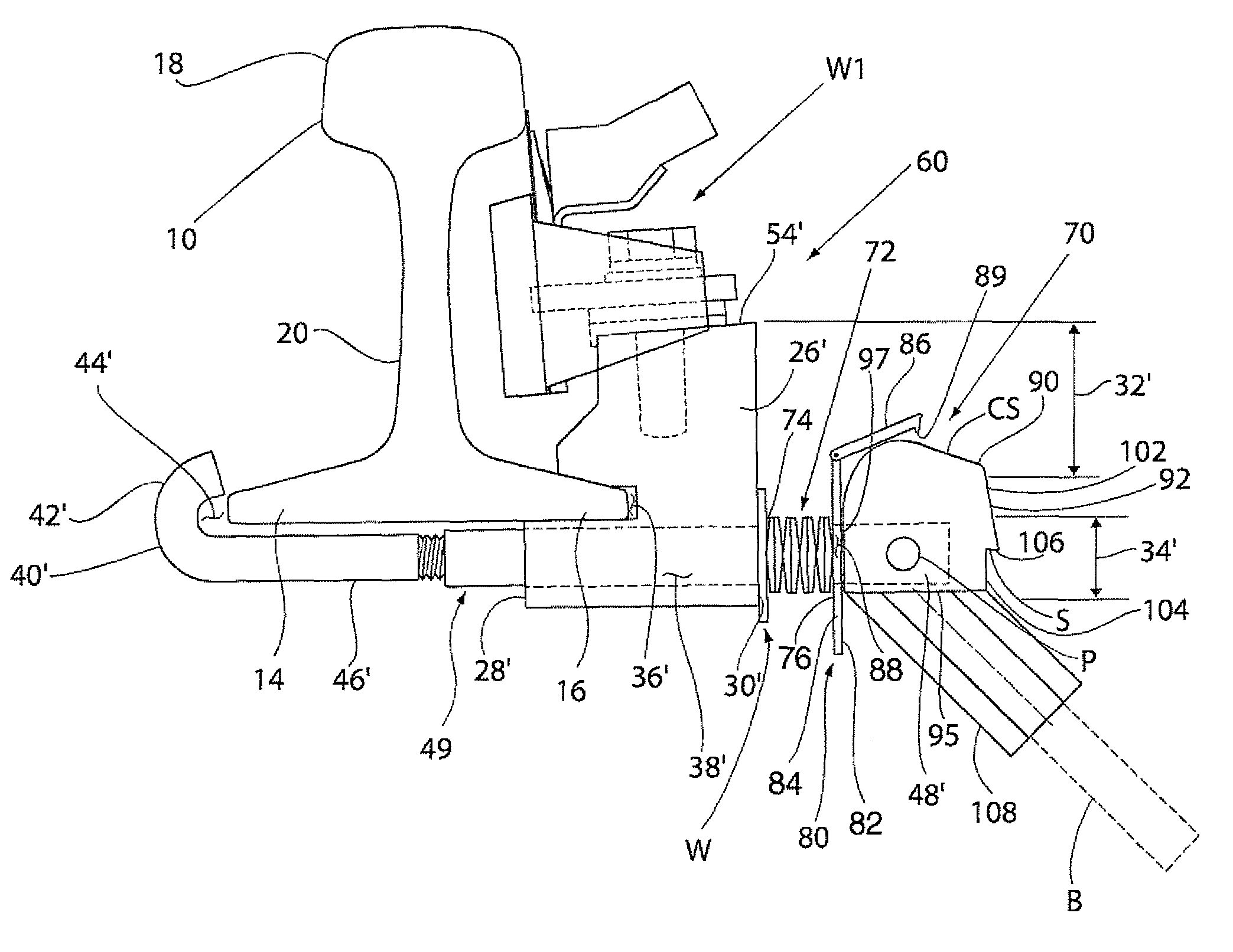
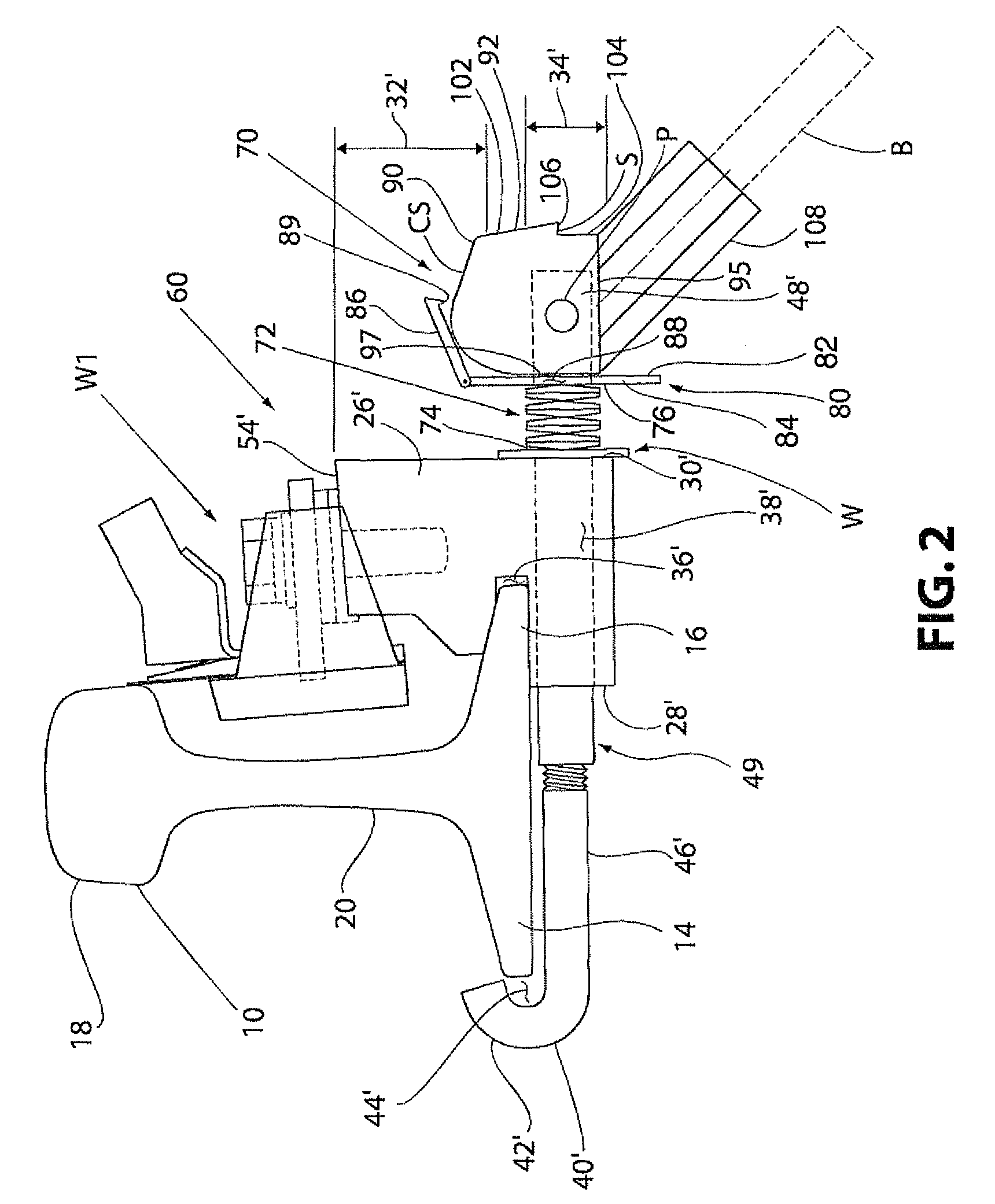
[0036]FIGS. 4 and 5 show a mounting clamp 110 that is similar to mounting clamp 60, except for the differences noted below. Like reference numerals are used for like parts. Instead of clamp 60 having a J-bolt 40′ with a hooked section 42′, clamp 110 includes a bolt 40″ having only a straight section 46′ that can be threaded at an end E thereof to receive a base receiving member 112 defining a recess portion 114 therein for receiving the base flange 14 of the railroad rail 10. The member 112 includes a body 116 having a first section 118 and a second section 120 with the recess portion 114 being defined therebetween. A bore 122 (shown in phantom) is defined in the first section 118 for receiving the straight section 46′ of the bolt 40″. The bore 122 may be internally threaded to longitudinally adjust along the straight section 46′ of the bolt 40″. The straight section 46′ of the bolt 40″ includes a head portion N, which may be a nut positioned at the end E, to secure the member 112 t...

third embodiment

[0037]FIGS. 6 and 7 show a mounting clamp 130 that is similar to mounting clamp 110, except for the differences noted below. Like reference numerals are used for like parts. Here, the cam member 90 and the bracket 80 are attached to the end portion 48′ of shaft section 49 of the bolt 40″ and the bracket 80 and cam member 90 are positioned adjacent the base receiving member 112. The straight section 46′ of the bolt 40″ includes a head portion N, such as a nut fastened to the end portion 48′ of the shaft 49 of the bolt 40″, that is configured to engage the second end 30′ of the clamp body 26′. The head portion N may also be a fixed portion of the straight section 46′ of the bolt 40″ that extends radially outward from the bolt 40″. The second end 76 of the spring 70 abuts against the head portion N to prevent the spring 72 from coming off. The bore 122 of the base receiving member 112 receives the shaft section 49 of the bolt 40″ thereby allowing the shaft section 49 to move within the...


PUM

PropertyMeasurementUnit
lengthaaaaaaaaaa
sizeaaaaaaaaaa
angleaaaaaaaaaa

Abstract

A clamp device for mounting a rail device onto a railroad rail includes a clamp body having an upper section and a lower section. The clamp body defines a recess portion between the upper and lower sections and a bore extending through the lower section of the clamp body. A bolt having a first end and a second end extends through the bore of the clamp body. The clamp device also includes a quick release mechanism having a lever arm and a cam member pivotally connected to the second end of the bolt. The lever arm is connected to the cam member and has a clamped position and a released position whereby pivoting the lever arm from the released position to the clamped position draws the first end of the bolt and the clamp body together.

Description

CROSS-REFERENCE TO RELATED APPLICATION[0001]This application claims the benefit of U.S. Provisional Application No. 61 / 098,281, filed Sep. 19, 2008, the entire content of which is hereby incorporated by reference.BACKGROUND OF THE INVENTION[0002]1. Field of the Invention[0003]This invention relates to a clamp device and, more particularly, to a clamping device for maintaining a rail device in position with respect to a railroad rail.[0004]2. Description of the Prior Art[0005]In the operation of railroads, it has long been the practice to apply lubricant or friction modifying materials onto railroad rails, such as to the top of the rails or sides of the rails at curves, turnouts, switches, and in some cases, the sections of the track immediately before a switch, and periodically spaced along the length of the track. Reference may be made to U.S. Pat. Nos. 5,348,120 and 5,394,958 and U.S. Pat. Application Pub. No. 2008 / 0223661, which are hereby incorporated by reference, for a dissert...

Claims


Application Information

Patent Timeline
Patent Type & Authority Patents(United States)
IPC IPC(8): B61K3/00
CPCB61K3/00Y10T29/49959
Inventor SINGLETON, STEVEN D.URMSON, JR., W. THOMASPETRIE, CHARLES A.LUCKE, CHRISTOPHER ALAN
Owner L B FOSTER RAIL TECH INC
Why Eureka
Try Eureka