Closure lock

a technology of locking mechanism and lock body, which is applied in the direction of cleaning equipment, washing/rinsing machine details, centrifuges, etc., can solve the problems of difficult operation of this type of locking mechanism, and the configuration is typically quite complex, and achieves the effect of simple configuration and convenient locking

Active Publication Date: 2014-07-22
EPPENDORF SE
View PDF28 Cites 2 Cited by
  • Summary
  • Abstract
  • Description
  • Claims
  • Application Information

AI Technical Summary

Benefits of technology

[0006]Thus, it is an object of the present invention to provide a closure lock, which is simple in configuration, facilitates secure locking also under high loads as they can occur, for example, for centrifuges, and which does not require various inputs for securing the functions of the closure lock.

Problems solved by technology

Closures of this type, however, are very difficult to operate, in particular for centrifuges.
However, it is disadvantageous in the known power locks, that they are typically quite complex in configuration and furthermore require plural inputs for securing the functions of the lock, namely, for example, an input for actuating the lock hook and another input for actuating the blocking of the lock hook.

Method used


Image

  • Closure lock
  • Closure lock
  • Closure lock

Examples


Embodiment Construction

[0039]In the following description, identical and like elements are designated with identical or similar reference numerals also when this is not explicitly illustrated.

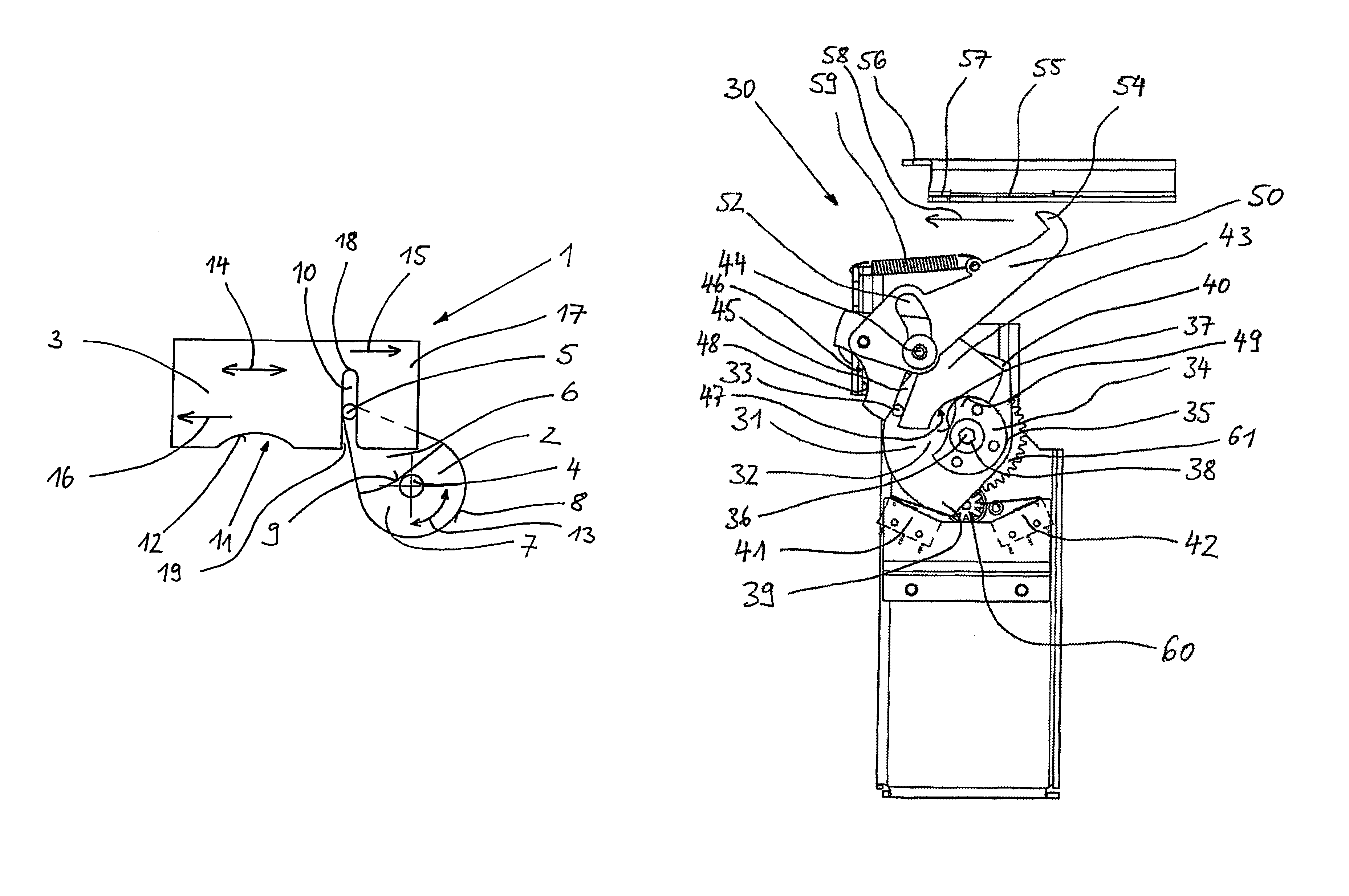
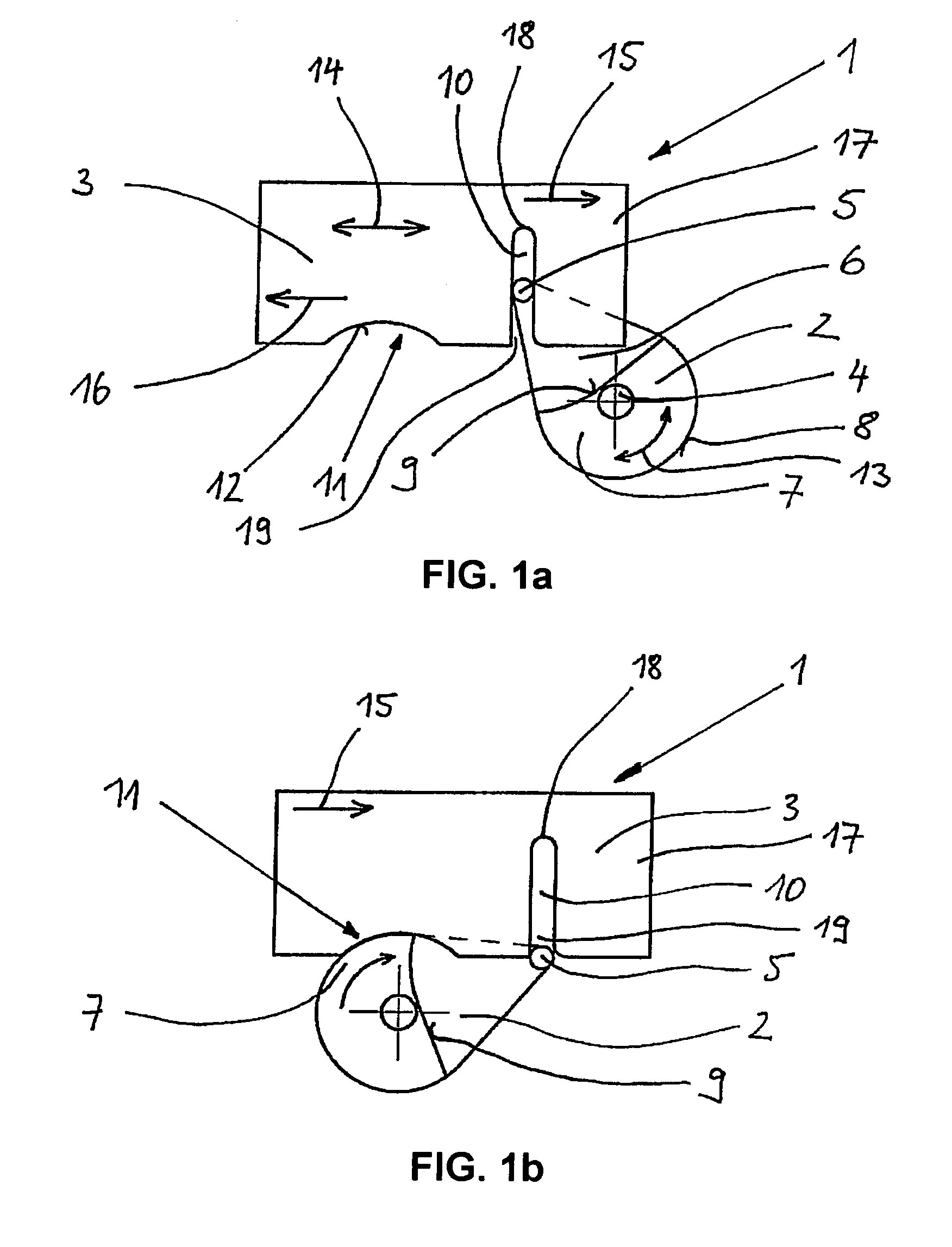
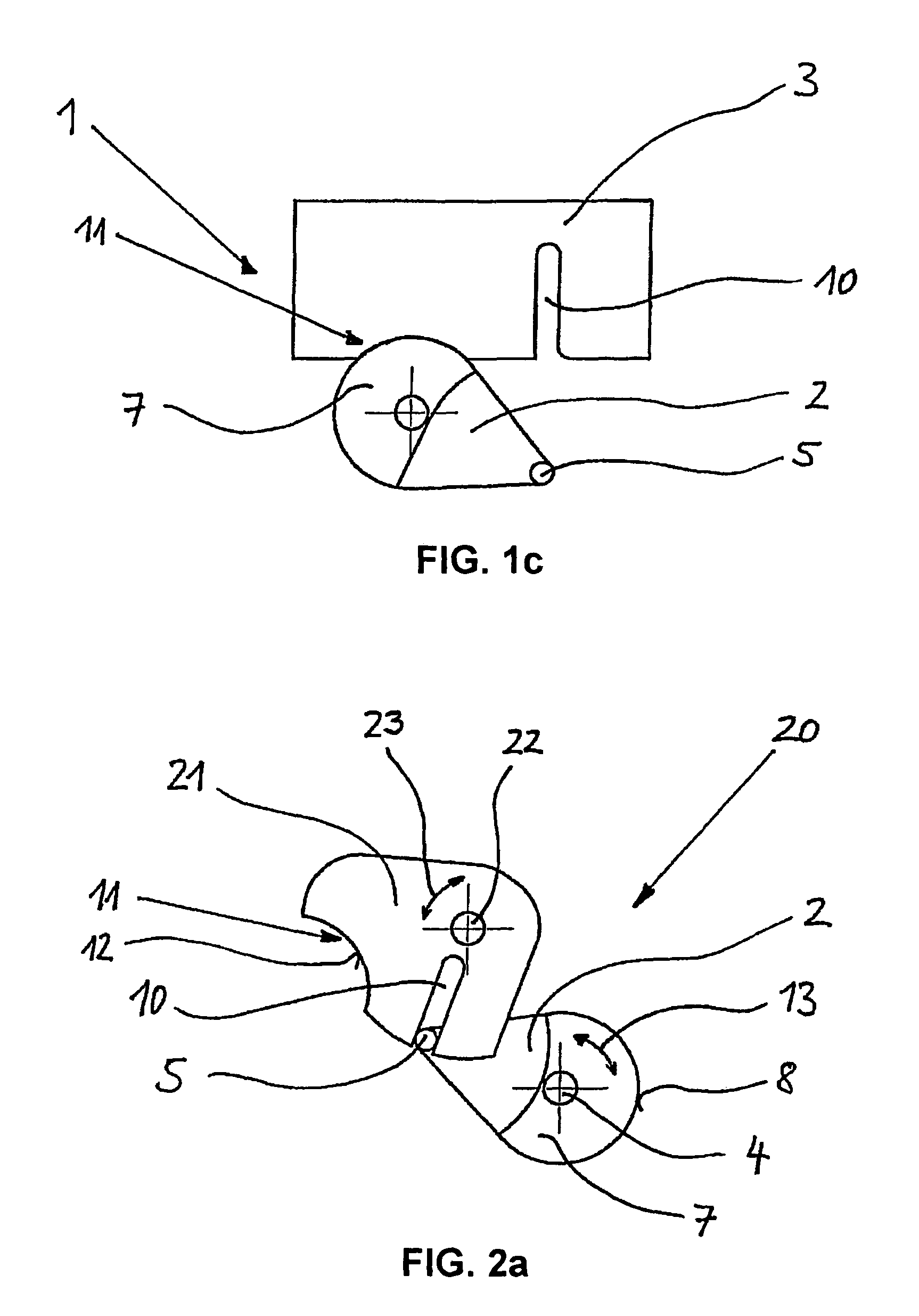
[0040]FIGS. 1a-1c illustrate a first embodiment of the lock 1 according to the invention in three different locking phases in a schematic depiction.

[0041]The lock 1 includes an input 2, which is actuated by a power drive, for example, a motor (not illustrated), and an output 3. The input 2 is configured as a lever wheel, which is arranged on the input rotation axle 4, so that the lever wheel is rotatable. The lever wheel 2 includes a lever element 5, which protrudes in a pin shape relative to the base 6 of the lever wheel 2. The lever wheel 2 additionally includes a circular segment 7 with a circular outer contour 8, which also protrudes relative to the base 6 of the lever wheel 2. Between the lever element 5 and the input rotation axle 4, the circular segment 7 is defined in portions through an outer contour 9, whic...


PUM


Abstract

A closure lock, in particular to a lock for a cover of a laboratory centrifuge and a housing of the laboratory centrifuge. The closure lock provides a particularly effective, loadable and safe lock which is not only actuatable through a power drive, but which also provides robust self blocking with respect to strong vibrations and high crash energies.

Description

RELATED APPLICATIONS[0001]This application claims priority from and incorporates by reference European Patent application EP 09015558.1-1252, filed on Dec. 16, 2009.FIELD OF THE INVENTION[0002]The present invention relates to a closure lock, in particular for locking a cover of a laboratory centrifuge at a housing of the laboratory centrifuge.BACKGROUND OF THE INVENTION[0003]Centrifuges, in particular laboratory centrifuges, have to be configured very safe with respect to locking the centrifuge cover at the centrifuge housing in order to minimize risk. The risk is represented by an unintentional opening of the centrifuge cover during operations, in particular represented by the rotor, which is then exposed and typically rotates at up to 16,000 RPM, and the risk is also represented by the samples arranged on the rotor, which are also exposed then. Also, for many other devices, a safe closure lock is advantageous for preventing accidents, for example, for laundry dryers, washing machi...

Claims


Application Information

Patent Timeline
Patent Type & Authority Patents(United States)
IPC IPC(8): E05B47/00A47L15/42E05C3/06B04B7/06F16P3/08E05B47/02
CPCF16P3/08E05B47/023B04B7/06E05B47/0012E05B2047/0025A47L15/4259E05B2047/003E05B2047/002Y10T292/1075Y10T292/08
Inventor MARSCHNER, KAIGRIMM, BERT-OLAF
Owner EPPENDORF SE
Why Eureka
Try Eureka