
Electrical connector

a technology of electrical connectors and connectors, applied in the direction of two-part coupling devices, coupling device connections, printed circuits, etc., can solve the problems of short electronic devices, inconvenient compactness, and inability to resist shock in the insulating housing, so as to achieve ideal reduction of the height of the electrical connectors

Active Publication Date: 2014-07-22
BING XU PRECISION
View PDF14 Cites 10 Cited by
  • Summary
  • Abstract
  • Description
  • Claims
  • Application Information

AI Technical Summary

Benefits of technology

The design reduces the height of the electrical connector, provides effective shock absorption, and accommodates the connector in space-limited environments by bending the cable, while ensuring secure fastening and support for the FFC and cable.

Problems solved by technology

However, a number of drawbacks have been found in the '459 patent.
Hence, it is not suitable for compact, short electronic devices.
Moreover, the insulating housing is not resistant to shock when it is subjected to strong external force exerted thereupon.

Method used


Image

  • Electrical connector
  • Electrical connector
  • Electrical connector

Examples


Embodiment Construction

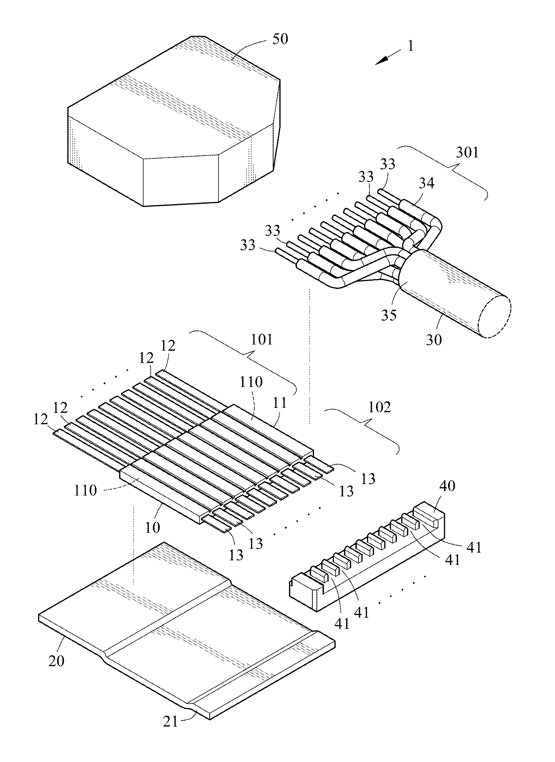
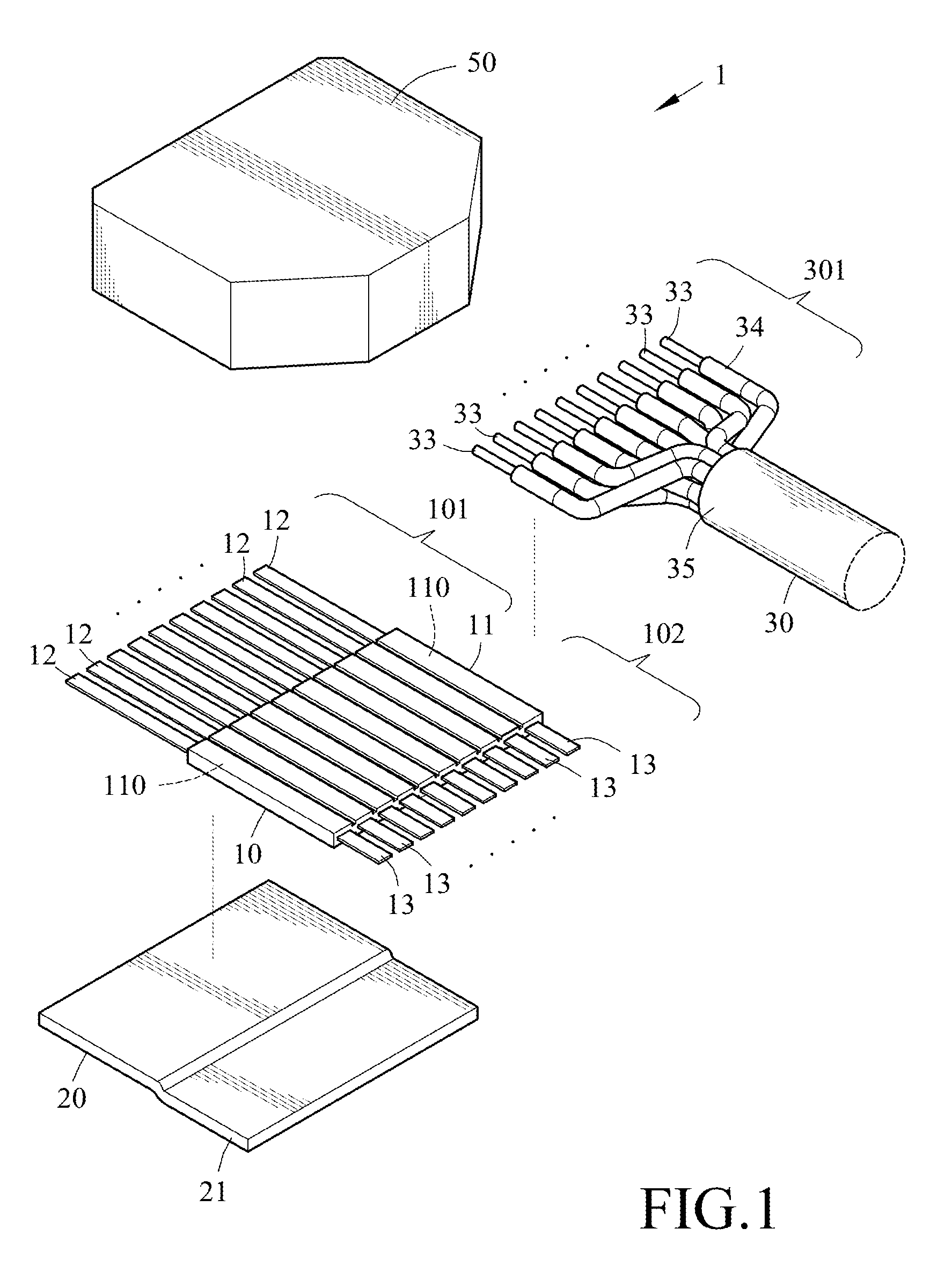
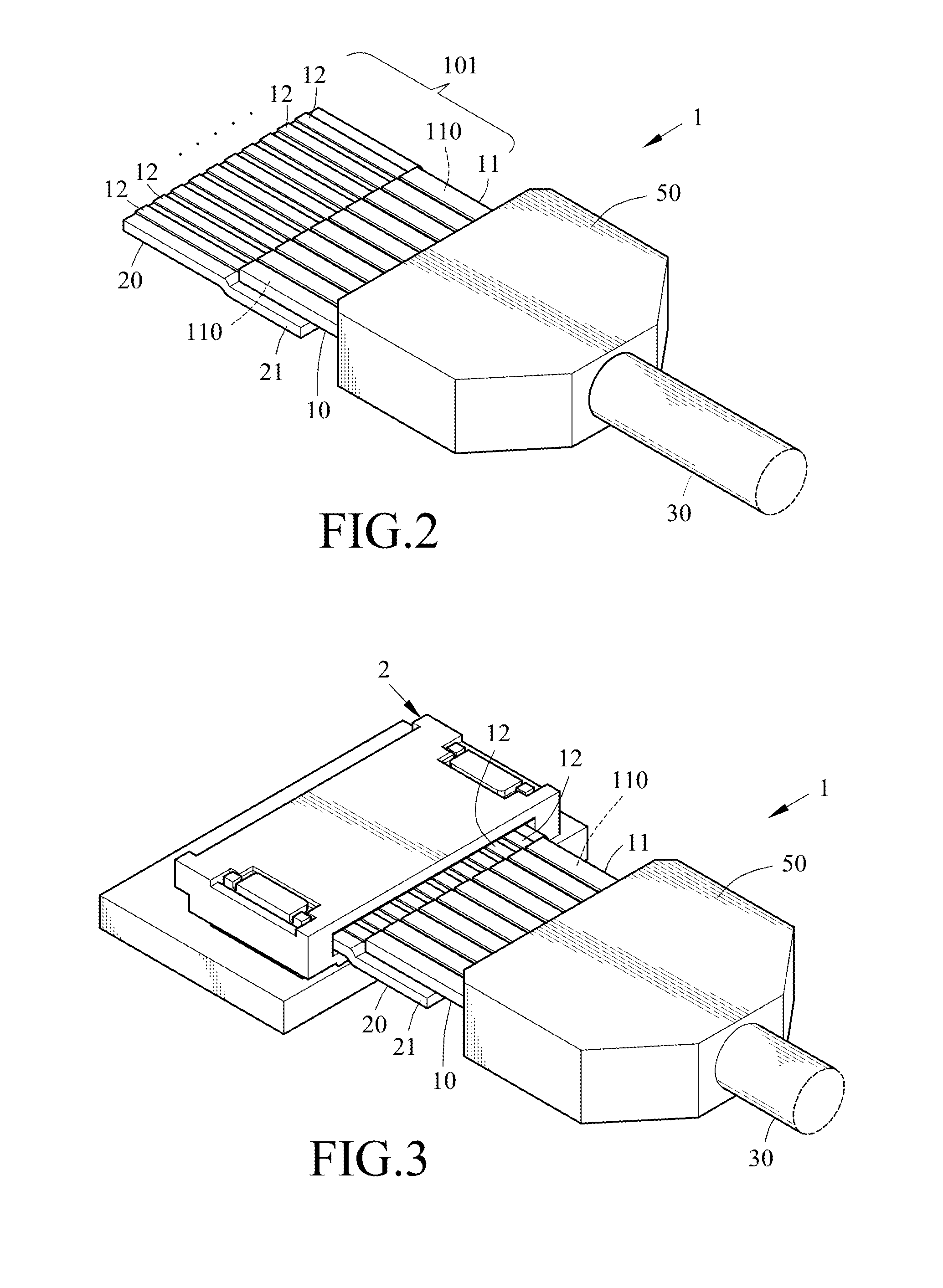
[0034]Referring to FIGS. 1 and 2, an electrical connector 1 in accordance with a first preferred embodiment of the invention comprises an FFC (flex flat cable) 10, a cylindrical electrical cable 30, and a connector housing 50. The FFC 10 comprises a rectangular first insulating layer 11 including a plurality of internal flat conductors 110 such as flat copper cables coated with tin, flat copper cables coated with gold, flat metal cables coated with tin, or flat metal cables coated with gold. Each flat conductor 110 is elongated and has a contact portion 12 at one end and a soldering portion 13 at the other end both not covered by the first insulating layer 11. The electrical cable 30 comprises a plurality of conductors 33 each having a cylindrical second insulating layer 34 therearound. The conductors 33 are electrically connected to the soldering portions 13. The connector housing 50 is provided to cover a rear portion 102 of the FFC 10 and a front end 301 of the electrical cable 3...


PUM


Abstract

An electrical connector is provided with an FFC including a first insulating layer including a plurality of internal flat conductors each being elongated and having an exposed contact portion at one end and an exposed soldering portion at the other end; an electrical cable including a plurality of conductors each having a second insulating layer therearound, the conductors electrically connected to the soldering portions; and a connector housing covering a rear portion of the FFC and a front end of the electrical cable for fastening the FFC and the electrical cable. A front portion of the FFC is provided with a protective plastic plate for fastening and supporting the contact portions of the FFC and the first insulating layer.

Description

BACKGROUND OF THE INVENTION[0001]1. Field of the Invention[0002]The invention relates to electrical connectors and more particularly to an electrical connector comprising a FFC (flex flat cable), an electrical cable electrically connected to the FFC, and a protective plastic plate in front of the FFC.[0003]2. Description of Related Art[0004]Taiwan Patent Publication No. M348,367 (its corresponding patents being China Patent No. 201266719 and U.S. Pat. No. 7,815,459) entitled “Cable connector assembly having a spacer and a bracket” disclosed a cable connector assembly comprising an insulating housing defining a base portion and a mating portion; a plurality of contacts received in the insulating housing and arranged in a line transversely; a cable connected to the contacts electrically; a cover made of an insulating material and mating with the insulating housing. The cover is attached to the base portion of the insulating housing. The cover and the mating portion are located at the ...

Claims


Application Information

Patent Timeline
Patent Type & Authority Patents(United States)
IPC IPC(8): H01R12/00H01R12/61H01R12/63
CPCH01R12/63H01R12/61H01R12/772
Inventor TSENG, TING CHANGLIN, WEN LUNG
Owner BING XU PRECISION
Learn More