Frame for speaker, speaker using same, and electronic apparatus and mobile device using speaker
a speaker and frame technology, applied in the field of loudspeaker frames, can solve problems such as the drawback of fair reliability to temperature change, and achieve the effect of improving the reliability to temperature chang
- Summary
- Abstract
- Description
- Claims
- Application Information
AI Technical Summary
Benefits of technology
Problems solved by technology
Method used
Image
Examples
exemplary embodiment 1
[0023]A loudspeaker frame in accordance with Exemplary Embodiment 1 will be described below.
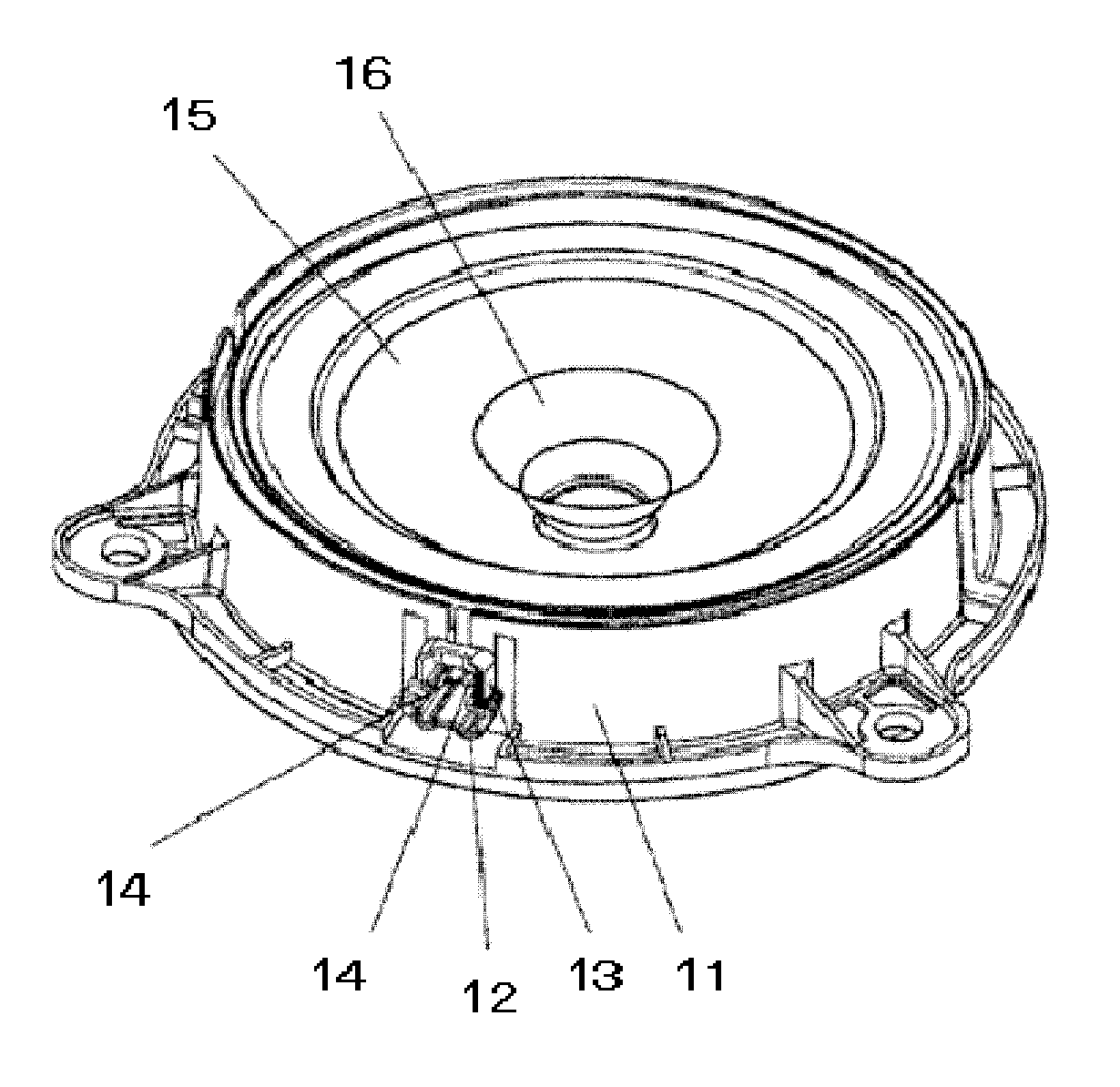
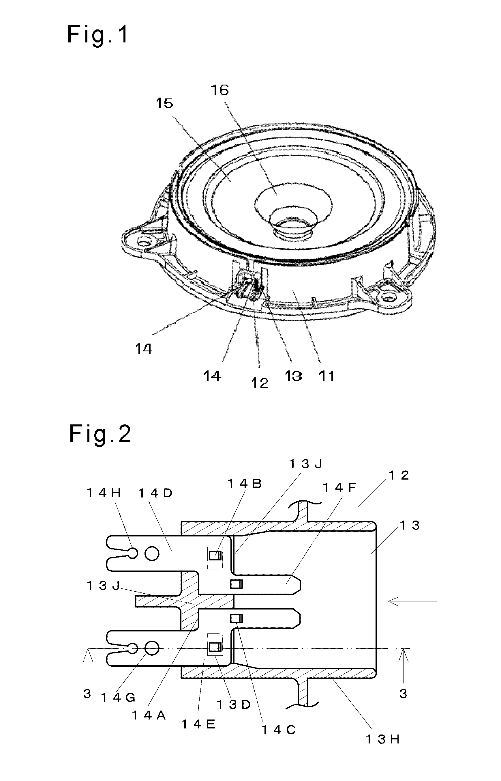
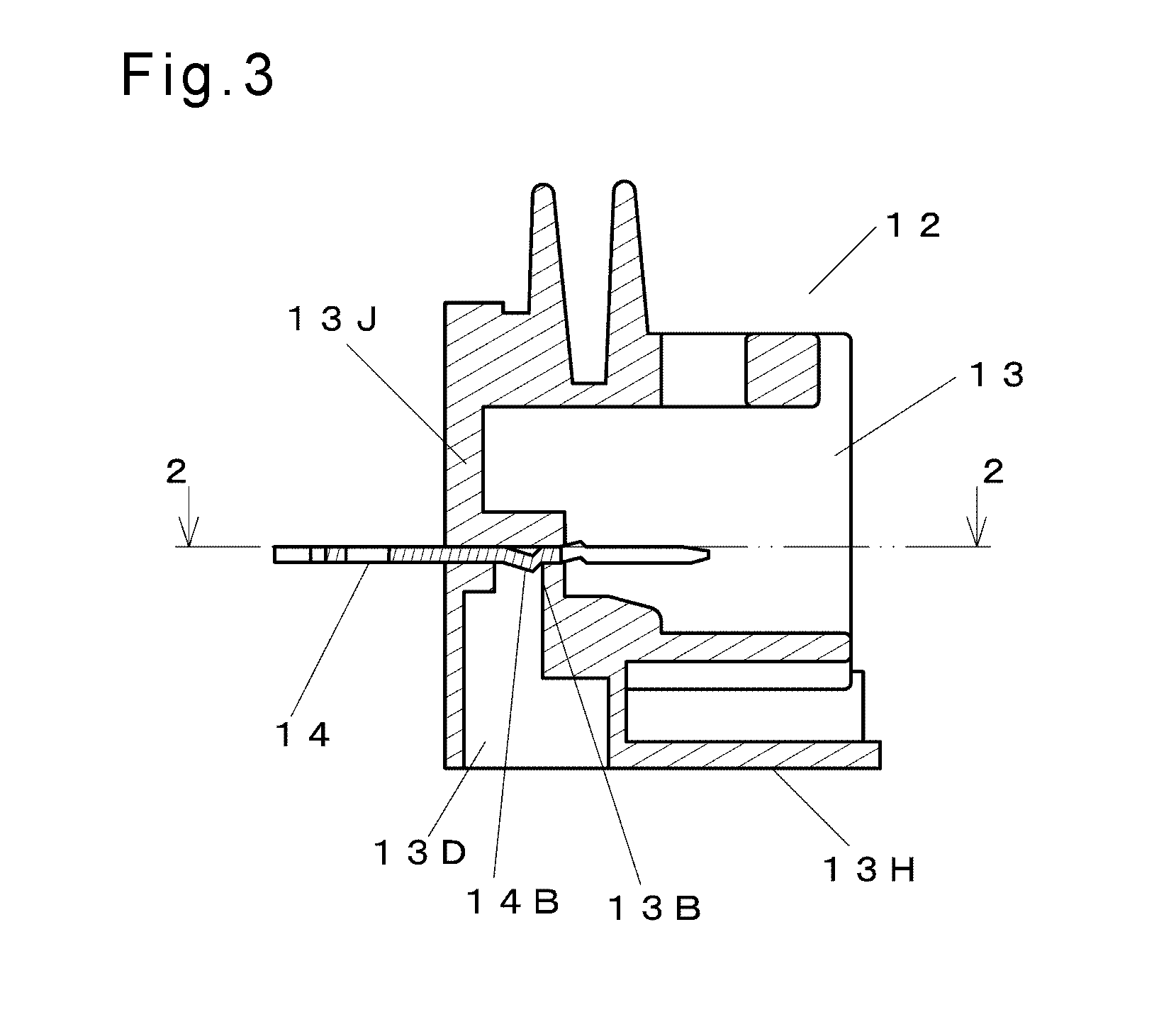
[0024]FIG. 1 is a perspective view of the loudspeaker frame in accordance with Embodiment 1 of the present invention. FIG. 2 is a sectional view of an enlarged essential part of a connector section of the loudspeaker frame in accordance with Embodiment 1. FIG. 3 is a sectional view of an enlarged essential part of the connector section cut along line 3-3 shown in FIG. 2.
[0025]FIG. 4A is a sectional view of an enlarged essential part of a connector housing of the loudspeaker frame in accordance with Embodiment 1. FIG. 4B is a front view of an eyelet terminal of the loudspeaker frame in accordance with Embodiment 1. In the following description, a plane direction refers to a direction viewed from a front (on a diaphragm side) of an assembled loudspeaker. In FIGS. 2 and 4, a lateral direction is an X-direction, and a vertical direction is a Y-direction. In FIG. 3, a vertical direction is a Z-dir...
exemplary embodiment 2
[0060]Exemplary Embodiment 2 will be demonstrated hereinafter. FIG. 7 is a sectional view of a loudspeaker in accordance with Embodiment 2 of the present invention. Magnetic circuit 24 used in the loudspeaker in accordance with Embodiment 2 is an inner magnet type magnetic circuit.
[0061]To be more specific, magnet 21 is sandwiched between upper plate 22 and yoke 23. Loudspeaker frame 11 in accordance with Embodiment 1 is coupled to yoke 23 of magnetic circuit 24.
[0062]The periphery of loudspeaker frame 11 is connected with an outer circumference of diaphragm 15. A first end of voice coil 28 is coupled to a center of diaphragm 15. A second end of voice coil 28 opposite to the first end is positioned in magnetic gap 25 of magnetic circuit 24. Sub-cone 16 is bonded to a front of voice coil 28.
[0063]Connector 12 is coupled with loudspeaker frame 11 as discussed in Embodiment 1. Eyelet terminal 14 is inserted into connector housing 13 to cause narrow section 14D to protrude from connecto...
exemplary embodiment 3
[0068]FIG. 8 is a schematic view of an electronic device in accordance with Exemplary Embodiment 3 of the present invention. According to Embodiment 3, audio mini-component system 44 is used as the typical electronic device. As shown in FIG. 8, a loudspeaker system is formed by incorporating loudspeakers 31 of the present invention into enclosure 41. This loudspeaker system includes amplifier 42 for amplifying an electric signal to be input to loudspeakers 31 and player 43 for supplying a source signal to be input into amplifier 42.
[0069]The above structure provides the electronic device that avoids the looseness between eyelet terminal 14 and connector housing 13 of loudspeaker 31, and the electronic device is resultantly free from abnormal sound caused by the looseness.
[0070]On top of that, since connector housing 13 is molded and simultaneously with frame 11 by injection molding the same resin, so that connector 12 is prevented from being taken off from frame 11 and the looseness...
PUM
 Abstract
Description
Claims
Application Information
 - R&D
- Intellectual Property
- Life Sciences
- Materials
- Tech Scout
- Unparalleled Data Quality
- Higher Quality Content
- 60% Fewer Hallucinations
Browse by: Latest US Patents, China's latest patents, Technical Efficacy Thesaurus, Application Domain, Technology Topic, Popular Technical Reports.
© 2025 PatSnap. All rights reserved.Legal|Privacy policy|Modern Slavery Act Transparency Statement|Sitemap|About US| Contact US: help@patsnap.com


