Articulated oral airway

a technology of oral airway and articulation, which is applied in the field of anesthesiology, can solve the problems of inability to permit the passage of an ett through the lumen, and the risk of inadvertent repositioning of the tube,

Active Publication Date: 2014-08-05
UNIV OF IOWA RES FOUND
View PDF12 Cites 2 Cited by
  • Summary
  • Abstract
  • Description
  • Claims
  • Application Information

AI Technical Summary

Benefits of technology

[0010]In accordance with one embodiment, an articulating oral airway which allows for both displacement of oropharyngeal obstructions and convenient placement of an ETT via the device.

Problems solved by technology

A significant disadvantage of this technique is that, for an image to be seen, an “airspace” (a space void of visual obstruction) must be created.
Two important disadvantages of this design are that 1) the static conformation of the distal end can not actively displace airway obstructions and 2) once the ETT is passed via the device, the proximal end of the tube must be disassembled to allow the device to be removed, carrying significant risk of inadvertent repositioning of the tube.
While addressing the first-listed disadvantage, the design of U.S. Pat. No. 5,443,063 does not address the second.
U.S. Pat. No. 4,553,540 is a device with upper and lower hinged / articulated segment which act together to displace oropharyngeal obstructions but, like U.S. Pat. No. 5,443,063, does not permit the passage of an ETT via its lumen.

Method used


Image

  • Articulated oral airway
  • Articulated oral airway
  • Articulated oral airway

Examples


first embodiment

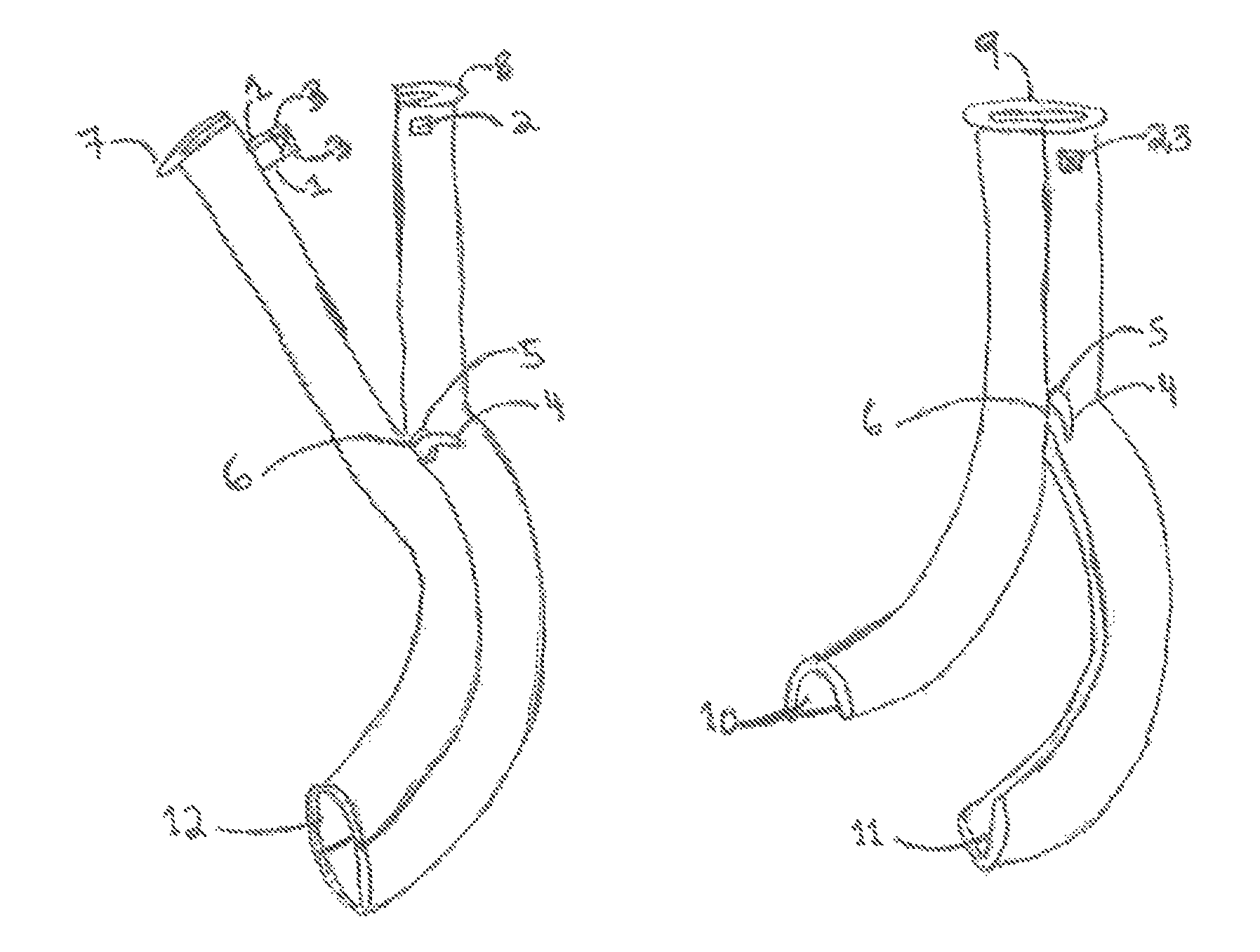
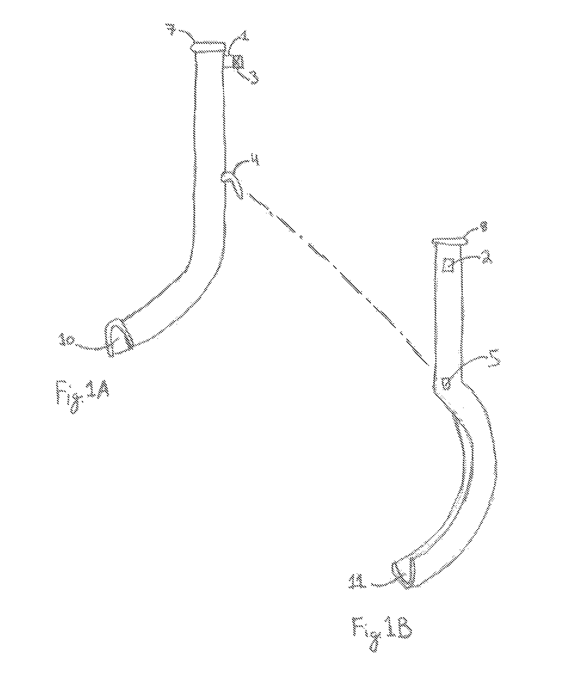
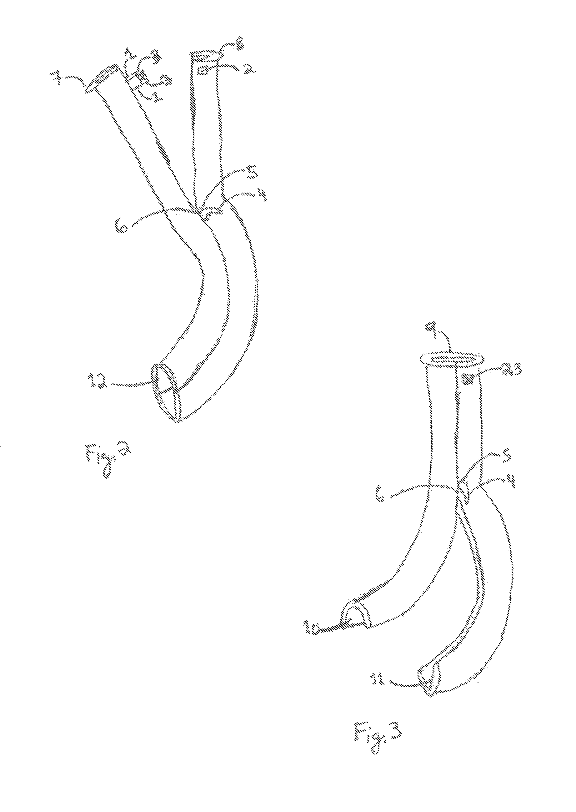
[0047]The manner of using the articulating oral airway begins with articulation of Parts A and B in the Open position (FIG. 2). This is accomplished by placing the articulating hooks 4 in the articulating hook receptacles 5. When this is done the device will be aligned to form an ovoid distal lumen 12. In this conformation the device is advanced into the oropharynx until resistance is felt. The point at which resistance is felt is typically when the articulating hook receptacles 5 reach the level of the teeth. At this point the lip abutments of Parts A and B are brought together as the device is inserted further. With the lip abutments 7 / 8 approximated the device will latch and stay in the Closed position (FIG. 3) as described above. In the Closed position the distal ends of the device will be separated with Part A displacing the tongue anteriorly, stenting open the oropharynx. Insertion is complete when the lip abutments abut the lips. Through the now formed proximal lumen an airwa...

second embodiment

[0049]The manner of using the Second Embodiment of articulating oral airway is identical to the First Embodiment with the following difference: With the device inserted, the oropharynx is now stented open and ventilation may be performed via a mask placed over the airway.

FIGS. 5 through 7

Third Embodiment

[0050]This embodiment of the invention is identical to the First Embodiment except the following difference: The latch tabs 1 and latch tab receptacles 2 are replaced with opposing magnets 13. When in the Closed position these magnets will serve the purpose of the latch tabs / latch tabs receptacles of the First Embodiment for keeping the device in the Closed position.

Operation

third embodiment

[0051]The manner of using this embodiment of the articulating oral airway is identical to the First Embodiment except for the following: When in the Closed position the magnets 13 of Part A and B hold the device in the Closed position. To remove the device the magnetic seal is broken by pulling the magnets / lip abutments apart. With the lip abutments 7 / 8 separated, the device returns to the Open position. From the Open position the articulating hooks are removed from the articulating hook receptacles and the device is separated into its component parts (Parts A and B) and removed from the mouth.

FIGS. 8 through 10

Fourth Embodiment

[0052]This embodiment of the invention is identical to the First Embodiment except the following difference: The articulating hook receptacles 5 are replaced with articulating hook bars 14 on either side of Part B. When joining Parts A and B together these bars will serve the purpose of the articulating hook receptacles of the First Embodiment as the point of...


PUM


Abstract

One embodiment of an oral airway comprised of two articulating parts which displace the tongue anteriorly and stent open the oropharynx. This device reversibly locks in a conformation which allows it to be used as a conduit for a fiberoptic scope or other airway device. An adjunct to airway management which can be used when mask ventilation or endotracheal intubation is indicated and can be removed easily after intubation without manipulation of the endotracheal tube. Other embodiments are described as shown.

Description

CROSS-REFERENCE TO RELATED APPLICATIONS[0001]This patent claims the benefit of provisional patent application Ser. No. 61 / 093,322, for “Articulated Intubating Airway,” filed 2008 Aug. 31 by the present inventor.FEDERALLY SPONSORED RESEARCH[0002]Not ApplicableSEQUENCE LISTING OR PROGRAM[0003]Not ApplicableBACKGROUND[0004]1. Field of Invention[0005]This invention generally relates to the field of Anesthesiology, specifically to airway management.[0006]2. Prior Art[0007]Flexible fiberoptic intubation of the trachea allows for placement of an endotracheal tube (ETT) with minimal manipulation of the patients airway. A significant disadvantage of this technique is that, for an image to be seen, an “airspace” (a space void of visual obstruction) must be created. If the tip of the fiberoptic scope is touching the patient's airway or any foreign objects in the patient's airway, the result would be analogous to leaving the lens cap on a camera and the necessary anatomy would not be seen. For ...

Claims


Application Information

Patent Timeline
Patent Type & Authority Patents(United States)
IPC IPC(8): A61M16/00A62B9/06
CPCA61M16/0488
Inventor ABRONS, RON, OWEN
Owner UNIV OF IOWA RES FOUND
Why Eureka
Try Eureka