IEC 61158-2 electrical circuit with water detection means comprising a physical layer attribute modifier

Inactive Publication Date: 2014-08-05
PEPPERL FUCHS GMBH
View PDF8 Cites 2 Cited by
  • Summary
  • Abstract
  • Description
  • Claims
  • Application Information

AI Technical Summary

Benefits of technology

[0027]The key advantage of the present invention is that the communication of the detection of water ingress is conducted using the existing electrical circuit and its physical layer monitoring means. There is therefore no need for extra Intrinsically Safe cabling, power, electronics or cable glands. Further, as the water detection means are basically autonomous, they can be adapted to detect high purity low conductivity water that an earth leakage detection system cannot. By positioning the water detection probes away from the terminals in the field device detection can also be made long before any damage is caused. There is also no requirement for any connection to the shield.
[0028]In a preferred constriction said device can have a normal operating orientation in which said water detection probes can be physically disposed below said terminals connecting said device function electronics to said electrical circuit. Therefore, the collection of water at the bottom of the enclosure can be detected before the terminals are under any real threat of immersion.
[0029]The monitoring means can be any of the known physical layer diagnostic systems (PLDS) which monitor trunk or spur currents and are able to monitor the bus signal level and noise influence. These levels are much higher than the effect that low conductivity water would have on the bus or spur, so known arrangements are not able to detect water ingress in a field device on their own, in particular because

Problems solved by technology

Water ingress into field devices is one fault that must be detected in order to prevent corrosion of the electrical terminals or cables inside the field device by electrolytic erosion, which can eventually lead to device failures.
In extreme cases submersion of the signal lines or terminals in water or other conductive fluids can lead to swift full signal or segment failures.
In addition, condensing water vapour inside the instrument enclosure usually infringes the humidity requirements of the instrument, as most specifications allow only 95% relative non-condensing humidity.
Unfortunately ingress of water into the terminal enclosures is a common occurrence in practice.
A load change and the effects of water bridging signal poles 5 would cause similar differential changes in the circuit 1, so a purely differential measurement would not be reliable.
However, these systems have a number of drawbacks.
First of all, they can only detect the presence of high conductivity water.
Cable length and voltage restrictions to meet the requirements of Intrinsic Safety make the detection of purer water impossible.
However such an event will start the process of galvanic corrosion which can cause a failure.
Dissolved metal trace elements leaking form the terminals and wire can quickly increase the conductivity of the water so it can be detected, but by then failure can occur before any evasive action can be taken.
The second main problem is that even if the water is conductive enough to be detected straight away, the poles 5 are already submerged when detection is made.
Submersion can rapidly lead to damage and signal problems, often before remedial action can be taken.
If the conductivity equivalent is 10 kOhms or less, the acceleration in conductivity due to localised metals dissolving into the solution can quickly result in an over current situation, and too rapidly to allow for proactive maintenance.
In oth

Method used


Image

  • IEC 61158-2 electrical circuit with water detection means comprising a physical layer attribute modifier
  • IEC 61158-2 electrical circuit with water detection means comprising a physical layer attribute modifier
  • IEC 61158-2 electrical circuit with water detection means comprising a physical layer attribute modifier

Examples


Example

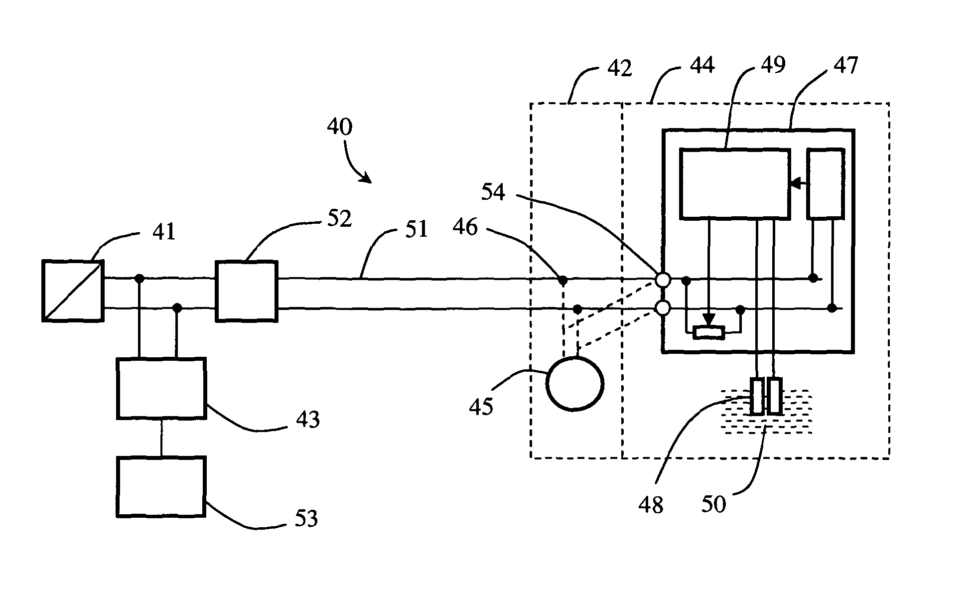
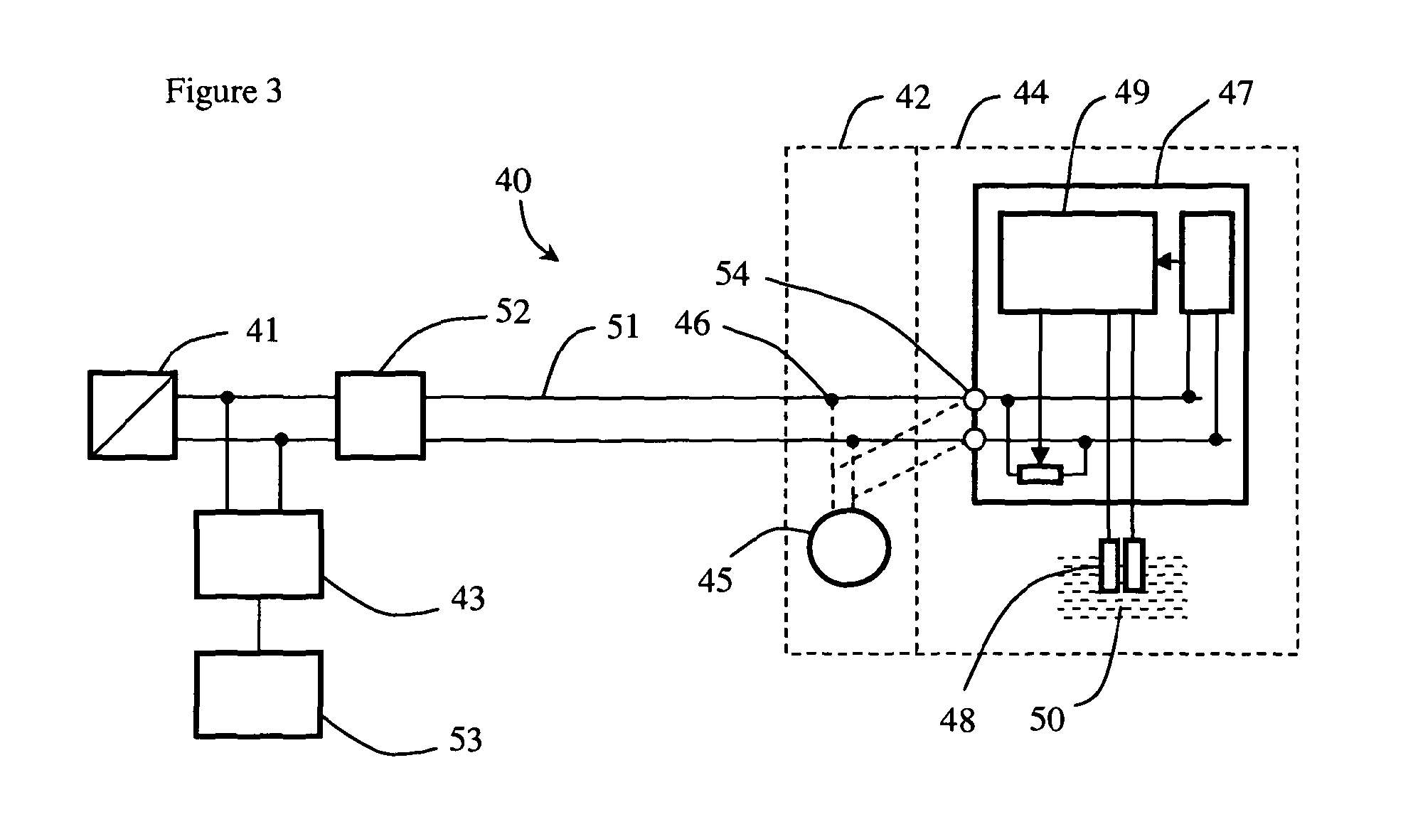
[0049]As shown in FIG. 3, an electrical circuit 40 confirming to the IEC 61158-2 standard comprises a Fieldbus power supply 41, a device 42 as a load thereof, and monitoring means adapted to monitor one or more physical layer attributes of the electrical circuit 40, in the form of physical layer attribute diagnostic module 43. The device 42 comprises an enclosure 44, device function electronics 45 disposed therein, and two terminals 46 connecting said device function electronics 45 to said electrical circuit 40. Water detection means 47 is disposed inside said enclosure 44, and comprises water detection probes 48 and a physical layer attribute modifier 49 mounted across said electrical circuit 40 in parallel with said device function electronics 45. When said water detection probes 48 detect water 50, said physical layer attribute modifier 49 makes a modification to a physical layer attribute of the electrical circuit 40, which modification is detectable by said monitoring means (43...


PUM


Abstract

An electrical circuit confirming to the IEC 61158-2 standard comprising a power supply, a device as a load thereof, and monitoring means adapted to monitor one or more physical layer attributes of the electrical circuit, in which the device comprises an enclosure, device function electronics disposed therein and two terminals connecting said device function electronics to said electrical circuit, in which water detection means is disposed inside said enclosure, and comprises water detection probes and a physical layer attribute modifier mounted across said electrical circuit in parallel with said device function electronics, and in which when said water detection probes detect water said physical layer attribute modifier makes a modification to a physical layer attribute of the electrical circuit, which modification is detectable by said monitoring means.

Description

CROSS-REFERENCE TO RELATED APPLICATIONS[0001]The present application is a national phase entry under 35 U.S.C. §371 of International Application No. PCT / GB2010 / 001347 filed Jul. 14, 2010, published in English, which claims priority from Great Britain Patent Application No. 0912444.7 filed Jul. 17, 2009, all of which are incorporated herein by reference.BACKGROUND OF THE INVENTION[0002]This invention relates to an electrical circuit conforming to the IEC 61158-2 standard with water detection means comprising a physical layer attribute modifier, for use in detecting the ingress of water into field devices in an Intrinsically Safe area.[0003]Fieldbus (or field bus) is the name of a family of industrial computer network protocols used for real-time distributed control, now standardized as IEC 61158. A complex automated industrial system, for example a fuel refinery, usually needs an organized hierarchy of controller systems to function. In this hierarchy there is a Human Machine Interfa...

Claims


Application Information

Patent Timeline
IPC IPC(8): G01R27/08A61M5/168B67D3/00G01M3/04G01M3/16G01N27/04G01N27/06G01N33/18G08B21/00
CPCG01M3/16G01M3/045G01N33/1886G01N27/06A61M5/16831B67D3/00G01N27/048
Inventor KITCHENER, RENATOROGOLL, GUNTHER
Owner PEPPERL FUCHS GMBH
Why Eureka
Try Eureka