
Fence tape

Active Publication Date: 2005-03-03
KUCHARCO
View PDF34 Cites 3 Cited by
  • Summary
  • Abstract
  • Description
  • Claims
  • Application Information

AI Technical Summary

Benefits of technology

[0008] The present invention provides a single composite web structure in the form of a flexible tape or ribbon which may be brightly colored and marked with “caution” or other words or symbols to visually give a warning. However, in addition, it provides integral cross members that are supported from the tape when the tape is held generally horizontally in place. The cross members are integral and are formed from the same tape. The cross members may be full or continuous cuts when the ribbon or tape is manufactured. However, the cross members are preferably formed by perforated cuts. This tape can be used alternately in conventional fashion or torn along the perforations to form the integral cross members. The cross members may be cut in various shapes, either uniform or variable, along the length of the ribbon and may be all of the same type or size or may be of different types or sizes. Additionally, holes may be punched at the ends of cut or perforated cut lines and may help to quickly identify the tear line and also to help confine the tears to the perforated areas. Additional holes within the web of the tape from which the cross members are cut may help to determine the fold line along which the cross member folds within the ribbon's web.
[0009] More specifically, the present invention concerns a tape barrier display or warning in which a tape or web of flexible material having generally parallel edges and substantially greater length than width is employed. Cuts are made into the tape at selected intervals to form slits along the tape defining cross members that extend generally along the length of the tape. The cuts may be completed slits so that the cross members are free to fall away from the tape. More frequently, it is anticipated the slits will be perforations that enable the cross members to be separated from the tape by tearing along the perforations. When the tape is deployed generally horizontally the cross members will fall vertically so as to provide cross members along the length of the resulting tape structure. Metallic or other substances can be added through any other means such as vapor deposition, lamination, printing, printing of conductive inks, or co-extruded particulate matter to make the tape readily detectable, or carry electrical currents. An application that would use this feature would be where the fencing material is buried underground. Such materials could be easily detected from the surface. In addition, the ability to conduct electricity could permit the fencing material to act as a heating element that melts snow on driveways or pavements.

Problems solved by technology

The fence does not inherently supply a cautionary message since the plastic lattice members are too small to support a meaningful visual display.
No product currently exists that produces a fence barrier that expands from a roll of flexible tape, ribbon, or strip.
Most of these are inappropriate for use as a fence barrier.

Method used


Image

  • Fence tape
  • Fence tape
  • Fence tape

Examples


Embodiment Construction

[0016] The invention is comprised of a flexible web material, typically of plastic such as polyethylene or vinyl, which is slit or die cut to allow the material to be deformed into a fencelike structure.

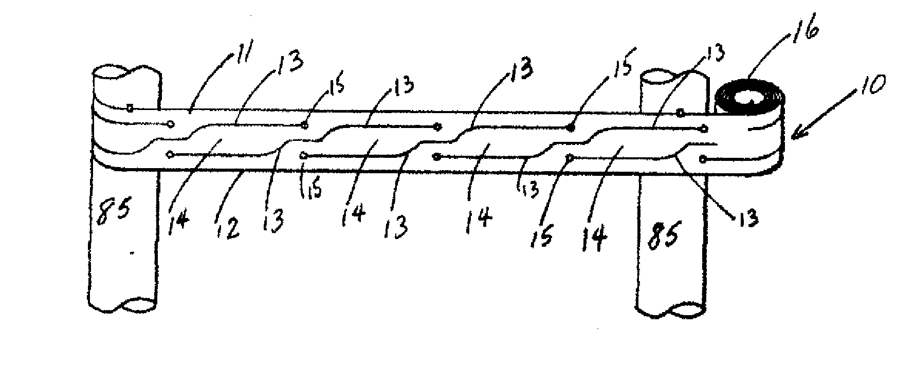
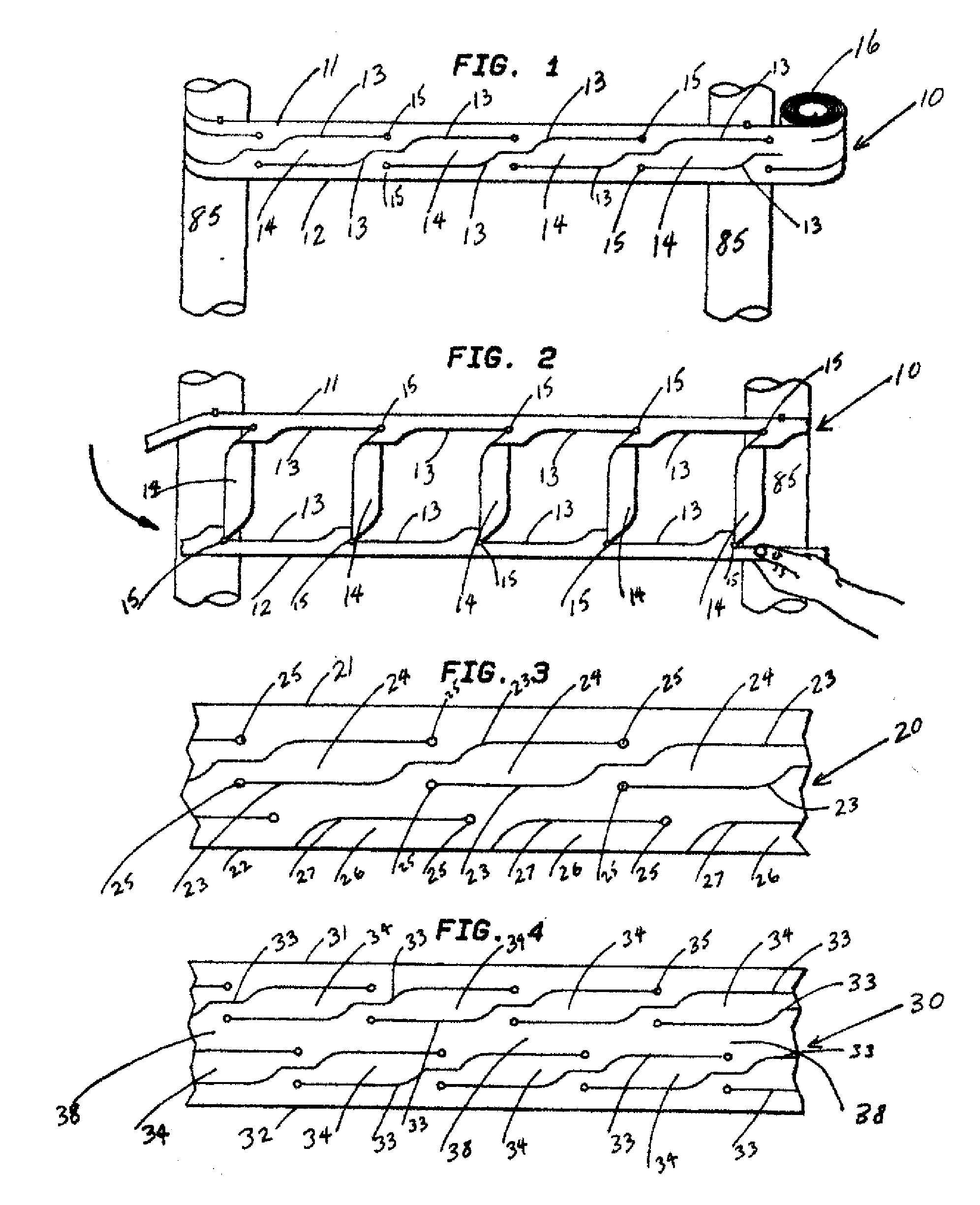
[0017]FIG. 1 shows the converted flexible web material 10 having a top edge 11 and bottom edge 12 with internal die cuts 13 defining undeployed cross members 14. Punched holes 15 act against stress concentration at the ends of the die cuts. Material 10 is attached, preferably by tying, although any means of attachment such as staples or tape may be used, to preferably vertical posts 85. The unused portion of the material 10, still rolled, is shown as 16.

[0018]FIG. 2 shows the converted flexible web material 10 attached to posts 85 at the top edge 11. The bottom edge 12 is pulled to the right and downward, causing die cuts 13 to open so that cross members 14 are deployed generally vertically to result in a fence like structure.

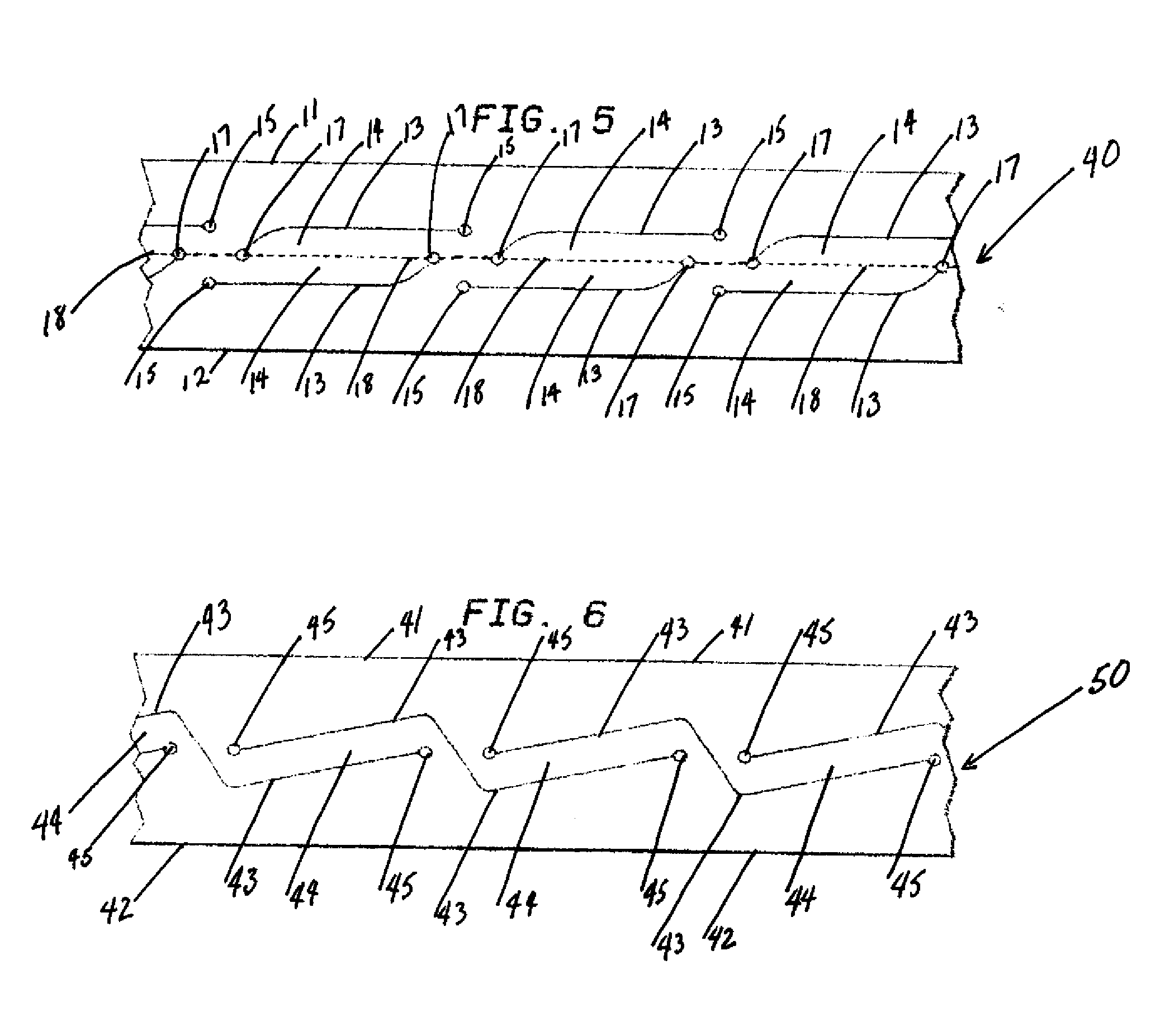
[0019] The embodiment of FIG. 3 works similarly to that...


PUM

PropertyMeasurementUnit
Electrical conductivityaaaaaaaaaa
Lengthaaaaaaaaaa
Flexibilityaaaaaaaaaa

Abstract

A tape barrier consisting of flexible material, has generally parallel edges and substantially greater length than width. Cuts are made into the tape at intervals along the tape forming slits that define cross members that extend generally along the length of the tape. The slits may be completed cuts so that the cross members are free to fall away from the tape or perforations that enable the cross members to be separated from the tape by tearing along the perforations. When the tape is deployed generally horizontally, the cross members will fall vertically so as to provide cross members along the length of the resulting tape structure.

Description

CROSS REFERENCE TO RELATED APPLICATIONS [0001] The present invention is related to my U.S. Pat. No. 5,244,715, entitled FLAG STRIP, the complete text of which is incorporated in its entirety by reference herein. Much of this material was disclosed in U.S. Provisional Patent Application No. 60 / 083,183, entitled FENCE TAPE, filed Apr. 27, 1998, now abandoned, and in its U.S. Non-Provisional counterpart application No. 09 / 300,771, entitled FENCE TAPE, also now abandoned. The complete text of said provisional and non-provisional applications are also incorporated in their entireties by reference herein.BACKGROUND OF INVENTION [0002] 1. Field of the Invention [0003] The present invention is an improvement over ribbons or strips used to mark off work or hazardous areas. More specifically the present invention provides for a fence type barrier to be formed by portions of the ribbon or strip. [0004] 2. Summary of the Prior Art [0005] Tapes, ribbons or strips, usually of highly flexible resi...

Claims


Application Information

Patent Timeline
IPC IPC(8): D04D9/00
CPCD04D9/00Y10T428/24273Y10T428/15Y10T428/24306Y10T428/24314Y10T428/12361
Inventor KUCHAR, DAVID M
Owner KUCHARCO
Learn More