Rolling Bearing

Inactive Publication Date: 2010-08-12
FLSMIDTH AS
View PDF6 Cites 2 Cited by
  • Summary
  • Abstract
  • Description
  • Claims
  • Application Information

AI Technical Summary

Benefits of technology

[0011]To minimize the space occupied by the rolling element in the circumferential direction of the bearing it is preferred that it comprises two opposite, plane side surfaces, each, when viewed cross-sectionally, constituting a chord in the imaginary circle. The two chords may be parallel, but in order to provide a good contact surface between two adjacent rolling elements when the bearing is in an extreme position subject to the maximum required angular rotation, and hence a self-locking effect, it is preferred that the two chords form a smaller angle between them so that the width of the rolling elements is greatest near the outer circular part. The size of the angle between the chords depends primarily on the number of rolling elements in the bearing which in turn depends on the required maximum angular rotation of the bearing. The smaller the required angular rotation of the bearing is, the shorter the arc lengths of the curved contact faces of the rolling elements with the outer and inner circular part, respectively, will have to be, and the higher is the number of rolling elements which can be accommodated. In for example an embodiment according to which the required angular rotation is

Problems solved by technology

If the known roller mill is used for grinding of particulate material, such as cement raw materials, cement clinker and similar materials, the hinged connection will be subjected to a relatively high pressure which, due to frictional forces between the parts of the hinged connection, will give rise to undesirable heat generation not immediately reducible by means of a lubricant because of the unilateral constant stress loading and the very small angular rotations back and forth of the bearing journal will not be sufficient to draw the lubricant into the zone of loading.
Of other commercially available bearing types mention can be made of a hydrodynamic slide bearing which cannot be used since there is no continuous rotation of the bearing journal, hence preventing the formation of a hydrodynamic lubricating film, as well as a hydrostatic radial bearing which from a technical v

Method used


Image

  • Rolling Bearing
  • Rolling Bearing
  • Rolling Bearing

Examples


Example

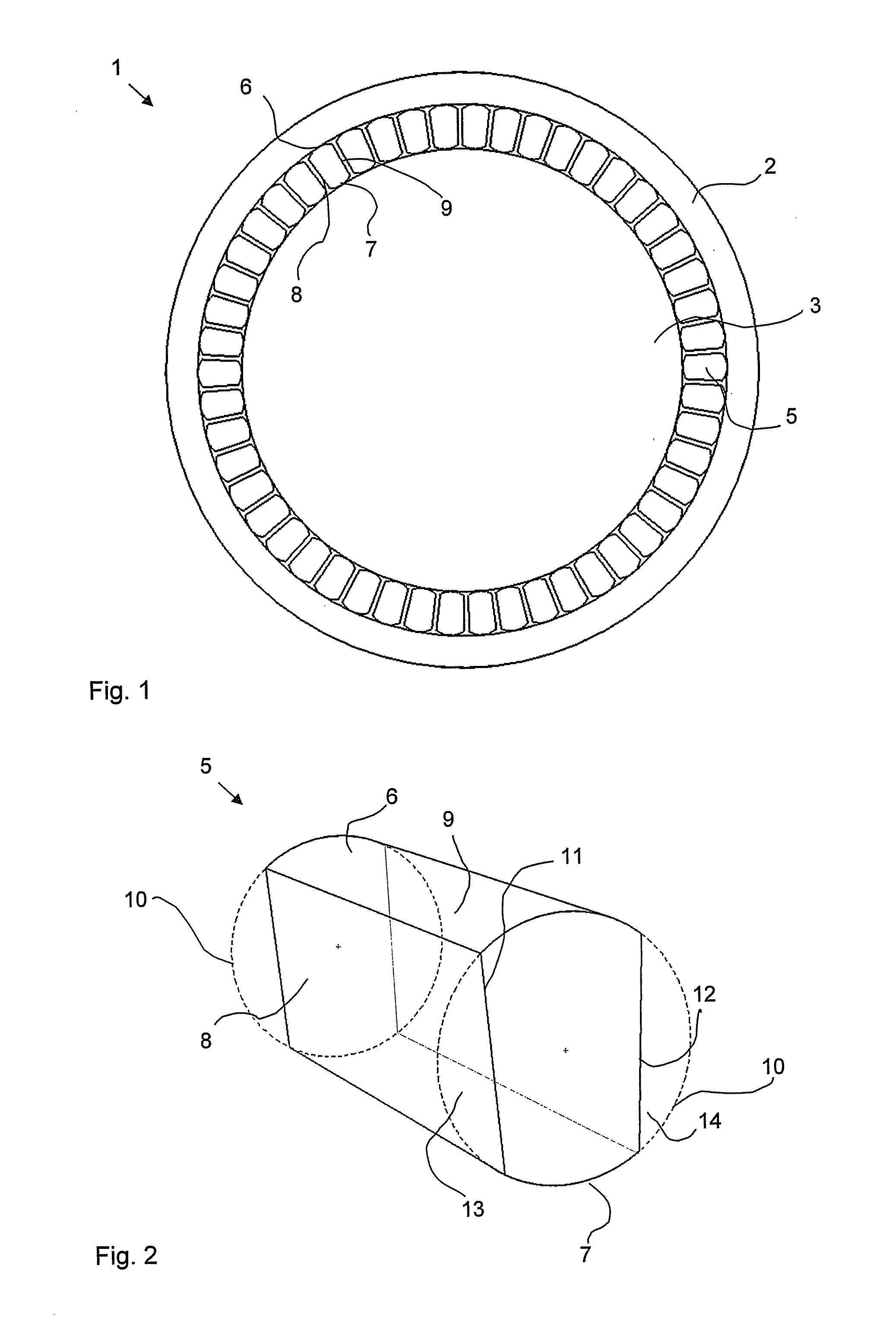
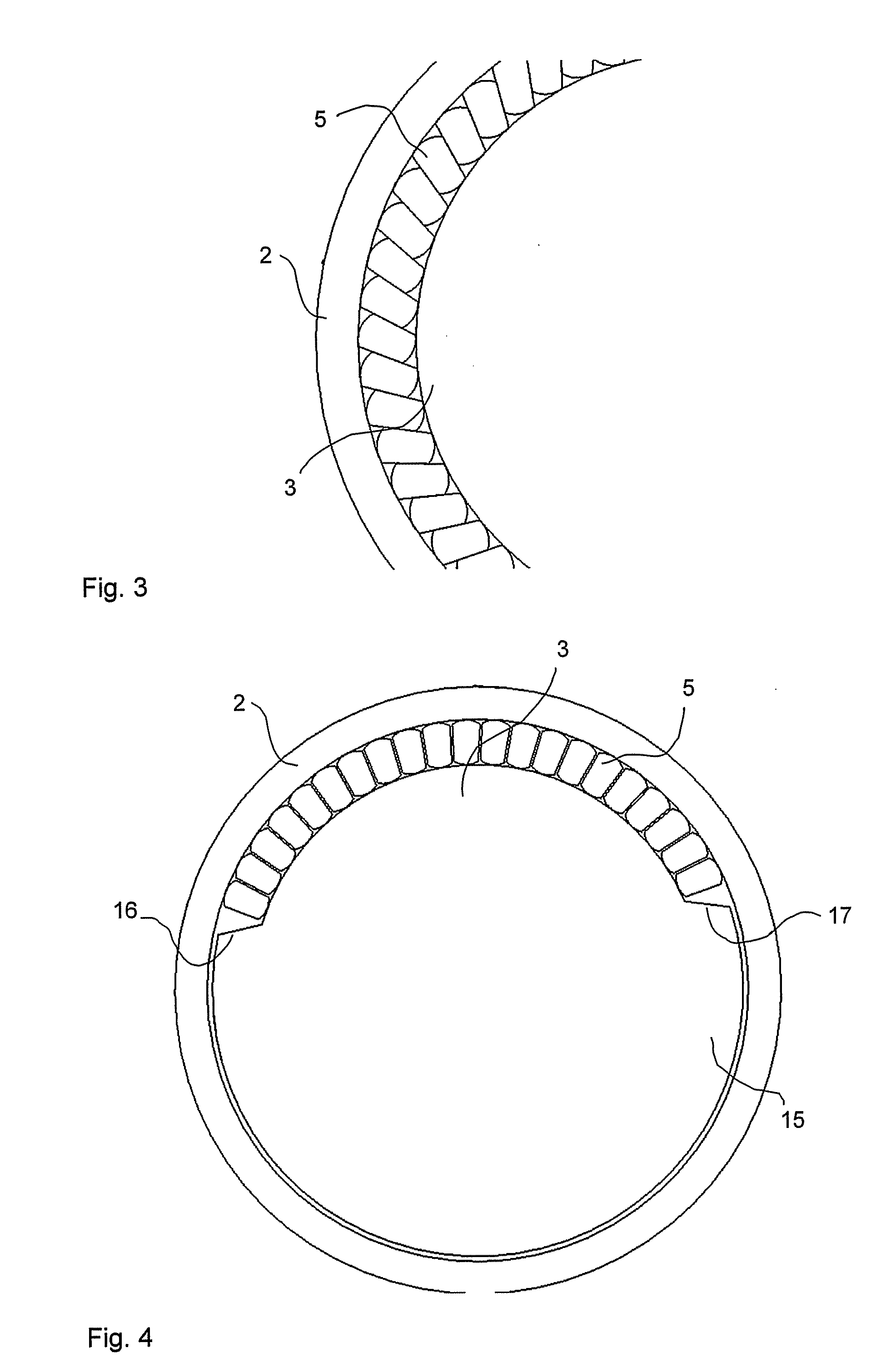
[0020]In FIG. 1 is seen a rolling bearing 1 according to the invention which comprises an outer circular part 2, an inner circular part 3 and a number of rolling elements 5 which are fitted between the outer part 2 and the inner part 3.

[0021]As is best illustrated in FIG. 2, the rolling elements 5 in the shown embodiment of the invention are formed as rods, each of which comprises four side faces 6, 7, 8 and 9, of which two opposite faces are curved side faces 6 and 7 which constitute arc lengths of the same imaginary circle 10, and which in the rolling bearing forms contact surfaces with the outer and the inner circular part 2, 3, respectively, and of which the two other opposite side faces 8 and 9 lie within the mentioned imaginary circle 10, being plane and facing respective adjacent rolling elements 5 as shown inter alia in FIG. 1.

[0022]Viewed cross-sectionally, each of the plane side faces 8 and 9 describe a chord 11, 12 in the imaginary circle 10. With reference to FIG. 2, the...


PUM

PropertyMeasurementUnit
Fractionaaaaaaaaaa
Widthaaaaaaaaaa
Areaaaaaaaaaaa

Abstract

Described is a rolling bearing (1) for a rocker arm, said rolling bearing comprising an at least partly circular outer part (2), an at least partly circular inner part (3) and a number of rolling elements (5) which are fitted between the outer part (2) and the inner part (3). The rolling bearing is peculiar in that at least one of the rolling elements (5) comprises two opposite, curved side faces (6, 7), which viewed in at least one cross-sectional constitutes arc lengths of the same imaginary circle (10), and which constitutes contact faces for the outer and the inner circular part (2, 3) respectively, and at least one side surface (8, 9), which lies within the mentioned imaginary circle (10).
It is hereby obtained that the number of rolling elements in the bearing can be increased, thereby reducing the load on each single rolling element subject to the same total load rate, thereby increasing the total load bearing capacity of the bearing. This is due to the fact that at least a part of the roller face of the traditional circular rollers which do not get into contact with the outer or inner part of the bearing through small reciprocating angular rotations is omitted thereby significantly reducing the space taken up by each of the rolling elements in the circumferential direction of the bearing.

Description

CROSS-REFERENCE TO RELATED APPLICATIONS[0001]This application is the United States national phase under 35 U.S.C. §371 of International Application No. PCT / EP2008 / 055164, filed on Apr. 28, 2008, and claiming priority to Danish Patent Application No. PA200700926, filed on Jun. 27, 2007. Both of those applications are incorporated by reference herein.BACKGROUND OF THE INVENTION[0002]1. Field of the Invention[0003]The present invention relates to a rolling bearing for a rocker arm, said rolling bearing comprising an at least partly circular outer part, an at least partly circular inner part and a number of rolling elements which are fitted between the outer part and the inner part.[0004]The invention also relates to the use of such a rolling bearing in a roller mill for grinding of particulate material, such as cement raw materials, cement clinker and similar materials, with said roller mill comprising a substantially horizontal grinding table and a roller set capable of revolving abou...

Claims


Application Information

Patent Timeline
IPC IPC(8): B02C15/00F16C19/24
CPCB02C15/007B02C15/14F16C2320/23F16C19/502F16C11/04F16C19/00
Inventor HANGHOJ, SORENTHRANBERG NISSEN, RASMUS
Owner FLSMIDTH AS
Why Eureka
Try Eureka