

Highlight color display architecture using enhanced dark state
a color display and enhanced dark state technology, applied in the field of high-reflectivity color display architecture, can solve the problem of only 50% of the maximum reflectivity of the white sta
Active Publication Date: 2014-08-05
E INK CORPORATION
View PDF87 Cites 61 Cited by
- Summary
- Abstract
- Description
- Claims
- Application Information
AI Technical Summary
Benefits of technology
The solution achieves high reflectance for the medium color state, at least five times that of the dark state, and allows for a standard active matrix array to drive the display, eliminating the need for sub-pixel architecture and enhancing color representation.
Problems solved by technology
It is fairly obvious that the disadvantage of such a technique is that the maximum reflectivity of the white state is only 50% since the sub-pixel with the color filter must be turned black for that state.
Method used
View moreImage
Smart ImageViewing Examples

Examples
example
[0066]FIGS. 10a-10c show photographs taken under a microscope of microcups displaying the white color (FIG. 10a), a medium blue color (FIG. 10b) and a blue color dark enough to appear black (FIG. 10c). In the experiment, white charged particles are dispersed in a dark blue solvent. The black lines indicate the partition wall area. The black lines are more pronounced in the photographs because these are enlarged images. In practice, the dark lines would not be visually detectable by a viewer.
[0067]The Dmax of the blue display fluid was 1.43 and the contrast ratio demonstrated by the color display was about 11.8, assuming 35% white.
Login to View More PUM
| Property | Measurement | Unit |
|---|---|---|
| reflectivity | aaaaa | aaaaa |
| transparent | aaaaa | aaaaa |
| color | aaaaa | aaaaa |
Abstract
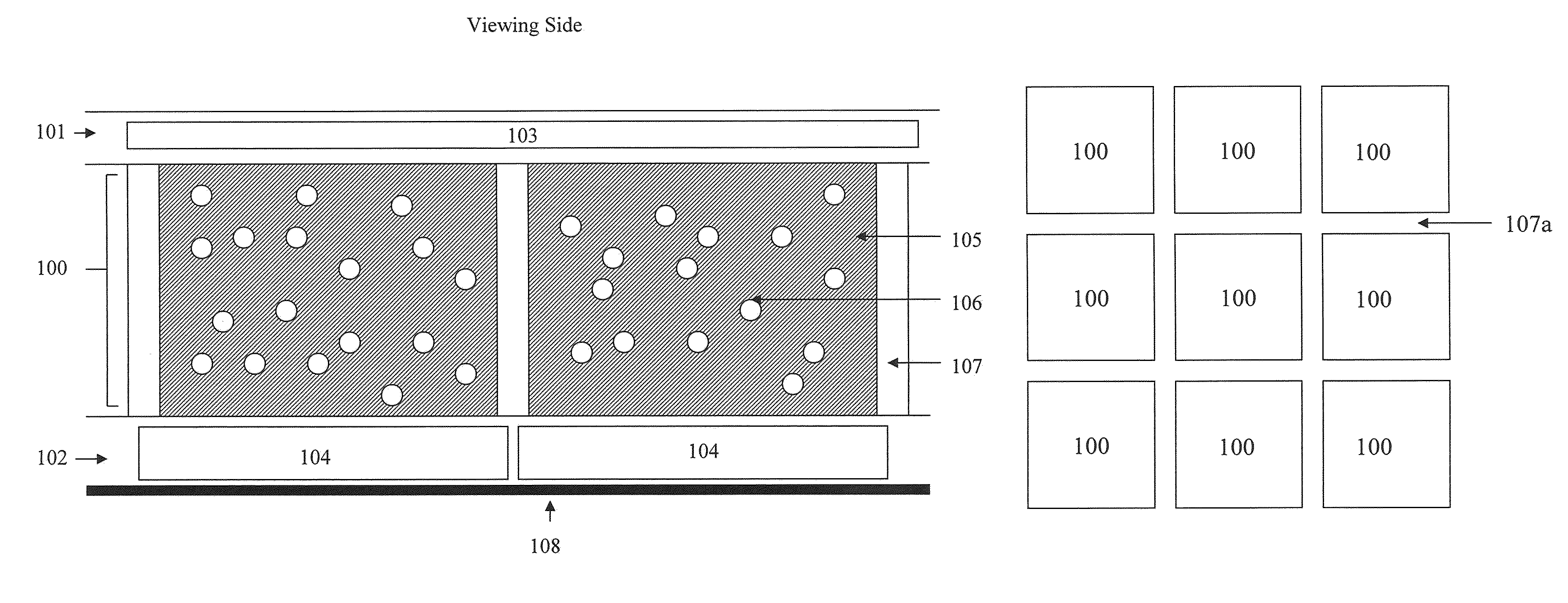
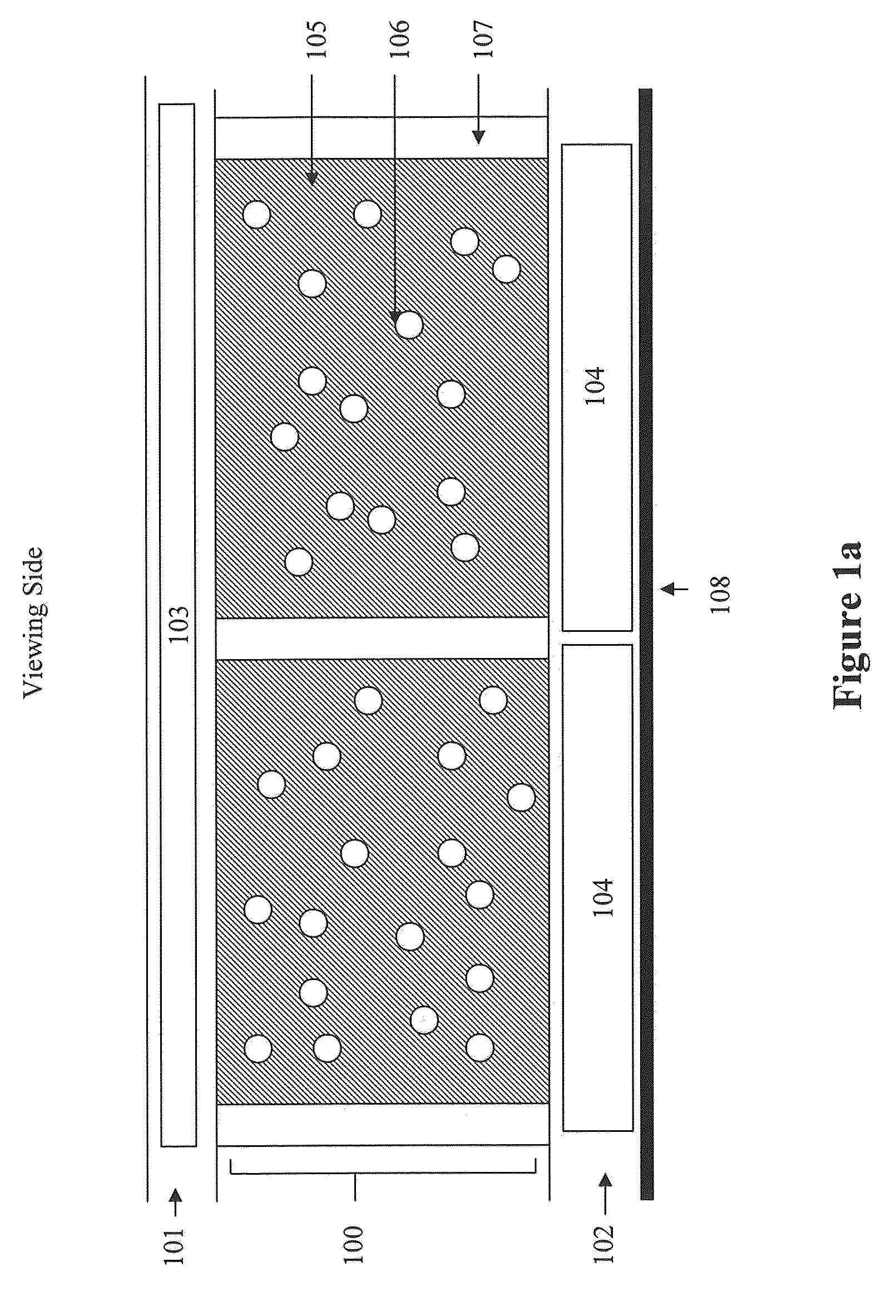
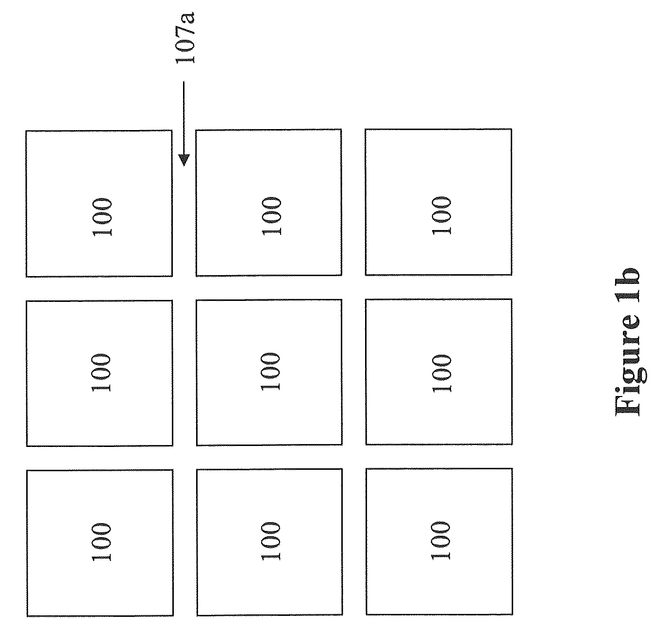
The present invention is directed to a highlight color display. One of the key features of the invention is the dark color of the display fluid filled in the microcups, which allows the dark state to appear black. There is no alignment required between the pixel electrodes and the microcups. In practice, a standard active matrix array may be used to drive the display device.
Description
[0001]This application claims priority to U.S. Provisional Application No. 61 / 141,574, filed Dec. 30, 2008; the content of which is incorporated herein by reference in its entirety.FIELD OF THE INVENTION[0002]The present invention is directed to highlight color display architecture using enhanced dark state.BACKGROUND OF THE INVENTION[0003]In order to achieve a highlight color display, color filters are often used. In one of the obvious options, each pixel has two sub-pixels and the two sub-pixels are based on two display cells capable of displaying black and white color states and only one of the sub-pixels has a color filter overlaid on top of a display cell. When a color state (e.g., red, green or blue) is desired, the sub-pixel with the color filter is turned on and the sub-pixel without a color filter is turned to the white or black state. When the black state is desired, both sub-pixels are turned to the black state. When the white state is desired, the sub-pixel without a col...
Claims
Login to View More Application Information
Patent Timeline
 Patent Type & AuthorityPatents(United States)
IPC IPC(8): G09G5/10G02F1/167
CPCG02F1/167G02F2001/1672G02F2001/1678G02F2203/30G02F1/1681
InventorSPRAGUE, ROBERT, A.
OwnerE INK CORPORATION