Elastic brace assembly and methods of use

a technology of elastic braces and assembly methods, applied in the field of elastic braces, can solve the problems of physical movement creating strains and injuries to joints, most of the sports of cutting or twisting, running, jumping, cutting or twisting today have the risk of damaging the knee, etc., to prevent plantar flexion or rolling of the ankle, reduce the extension of the limb, and prevent the effect of dorsiflection

Active Publication Date: 2014-08-19
KNEE X BRACE LLC
View PDF28 Cites 3 Cited by
  • Summary
  • Abstract
  • Description
  • Claims
  • Application Information

AI Technical Summary

Benefits of technology

[0013]Example embodiments of the elastic brace assembly utilize an elastic cross strap attached to mounting facilities about a joint to limit the extension of limbs about the joint. The cross strap has elastic properties that allow it to provide progressive resistance as the strap is stretched. The elastic cross strap assembly is positioned from a cross origin behind the joint to attachment points on upper and lower mounting facilities on the upper and lower limbs and provides an opposing tensile force that limits the extension of the mounting facilities and the limbs about a joint.
[0014]In example embodiments for other joints, the brace assembly may provide a resisting force that influences appendages about a joint. For example: for an ankle, the brace can be used to prevent dorsiflection, plantar flexion or rolling of the ankle; for a back, the brace can be used to prevent or support bending about the waist; for an elbow, the brace can be used to prevent hyperextension; and for a shoulder, the brace can be used to control movement of the humerus about the shoulder such as to restrict abduction and external rotation.
[0034]Some embodiments of the invention provide a method of supporting a wearer's joint, the method comprising the steps of securing a first portion of an elastic cross strap about one body portion joined to a second body portion at a wearer's joint, positioning the elastic cross strap about the joint to form a cross origin at a point of the joint and securing a second portion of the elastic cross strap about the second body portion at the joint whereby the elastic cross strap is capable of providing resistance to an extension of the wearer's body portions about the joint.

Problems solved by technology

Sports, physical labor and everyday physical movement can create strains and injuries to joints such as the shoulder, elbow, back, wrist, ankle and knee.
Specific to the knee, most of the running, jumping, cutting or twisting sports today have the risk of damaging the knee.
These injuries frequently involve a tearing the ACL in the knee.
With respect to these rigid braces however, many sports have rules in which players cannot have any metal or rigid devices on any part of their body to compete due to metal or hard structures that may cause injury to other players.
Smits does not disclose limiting extension of the brace with the strap.

Method used


Image

  • Elastic brace assembly and methods of use
  • Elastic brace assembly and methods of use
  • Elastic brace assembly and methods of use

Examples


Embodiment Construction

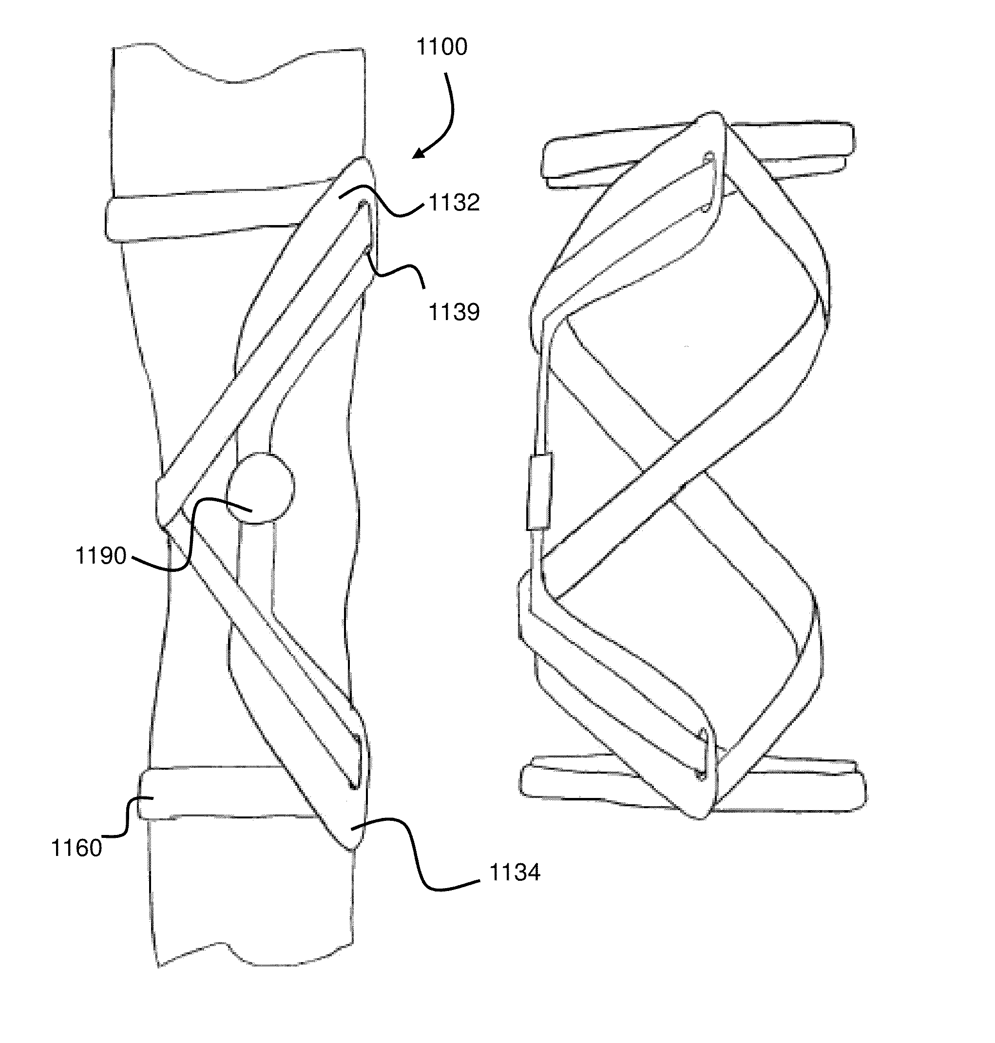
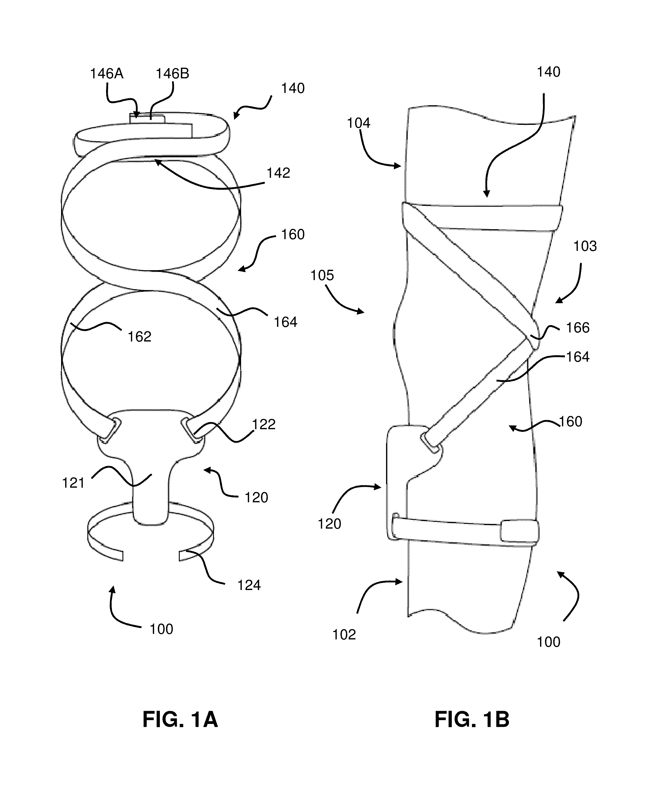
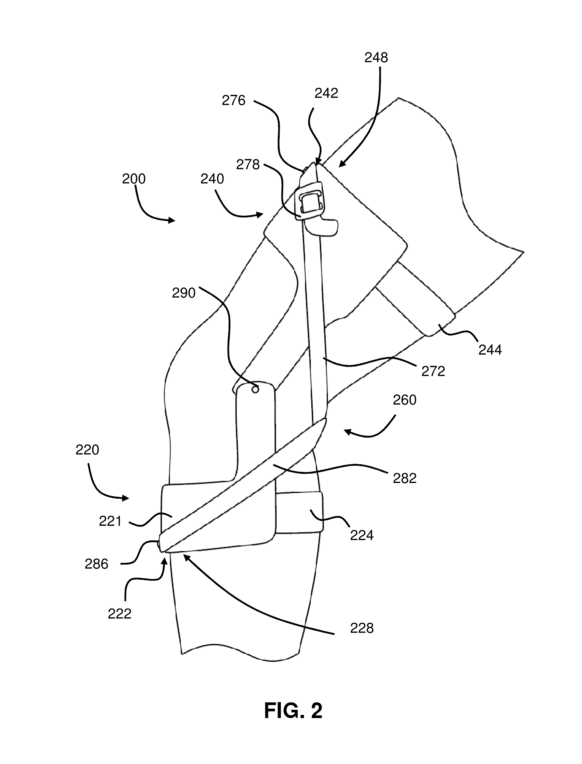
[0057]Although example embodiments are described in detail for use with knee bracing and reinforcement, it is understood that the methods and systems described can be used for similar medical situations where support of and resistance to moving joints may be needed. Examples of embodiments with other joints such as but not limited to the shoulder, elbow, back and ankle are also described and illustrated below. Notwithstanding the specific example embodiments set forth below, all such variations and modifications that would be envisioned by one of ordinary skill in the art are intended to fall within the scope of this disclosure.

[0058]Some embodiments of this new brace assembly comprise a non-rigid or semi-rigid brace utilizing an elastic cross strap to provide a progressive resisting force to joint movement such as hyperextension. Some embodiments of this brace assembly may include a flexible sleeve or other traditional brace components. Although some embodiments of the assembly do ...


PUM


Abstract

Example embodiments of the brace assembly utilize an elastic cross strap attached to mounting facilities about a joint to provide progressive resistance to the extension, flexion or other movement of body parts about the joint. In some embodiments for a knee joint, the brace assembly provides a progressive resisting force to resist hyperextension of the knee. Some embodiments of the assembly may be able to accommodate different joints, different size wearer's of the assembly and different tension settings such as for athletes during competition. Some embodiments of the brace assembly may be used bilaterally and can be made without metal bracing to comply with the requirements of some sports.

Description

CROSS-REFERENCE TO RELATED APPLICATIONS[0001]The present application is a Continuation in Part Application of PCT Application No. PCT / US09 / 67152, filed Dec. 8, 2009, PCT Application No. PCT / US09 / 67152 claims benefit of U.S. Provisional Application Ser. No. 61 / 262,723, filed Nov. 19, 2009, PCT Application No. PCT / US09 / 67152 also claims benefit of U.S. Provisional Application Ser. No. 61 / 263,737, filed Nov. 23, 2009, PCT Application No. PCT / US09 / 67152 is also a Continuation in Part Application of PCT Application No. PCT / US09 / 46183, filed Jun. 3, 2009, PCT Application No. PCT / US09 / 46183 claims benefit of U.S. Provisional Application Ser. No. 61 / 058,555, filed Jun. 3, 2008, and PCT Application No. PCT / US09 / 46183 claims benefit of U.S. Provisional Application Ser. No. 61 / 148,973, filed Feb. 1, 2009; the present application is also a Continuation in Part Application of U.S. patent application Ser. No. 12 / 993,258, filed Nov. 18, 2010, which is the U.S. National Stage application of Interna...

Claims


Application Information

Patent Timeline
Patent Type & Authority Patents(United States)
IPC IPC(8): A61F5/00
CPCA61F5/0102A61F2005/0179
Inventor PAULOS, LONNIE E.NELSON, KIM
Owner KNEE X BRACE LLC
Why Eureka
Try Eureka