

Temperature-stable LC oscillators and methods of oscillation at temperature null phase
a technology of inductor capacitor and oscillator, which is applied in the direction of oscillator, pulse automatic control, pulse technique, etc., can solve the problems of increasing the complexity of electronic systems, limiting the size and cost reduction of electronic systems, and the need for extra circuitry and techniques to decrease and/or compensate for frequency shifts
- Summary
- Abstract
- Description
- Claims
- Application Information
AI Technical Summary
Benefits of technology
Problems solved by technology
Method used
Image

Examples
Embodiment Construction
[0018]Summary
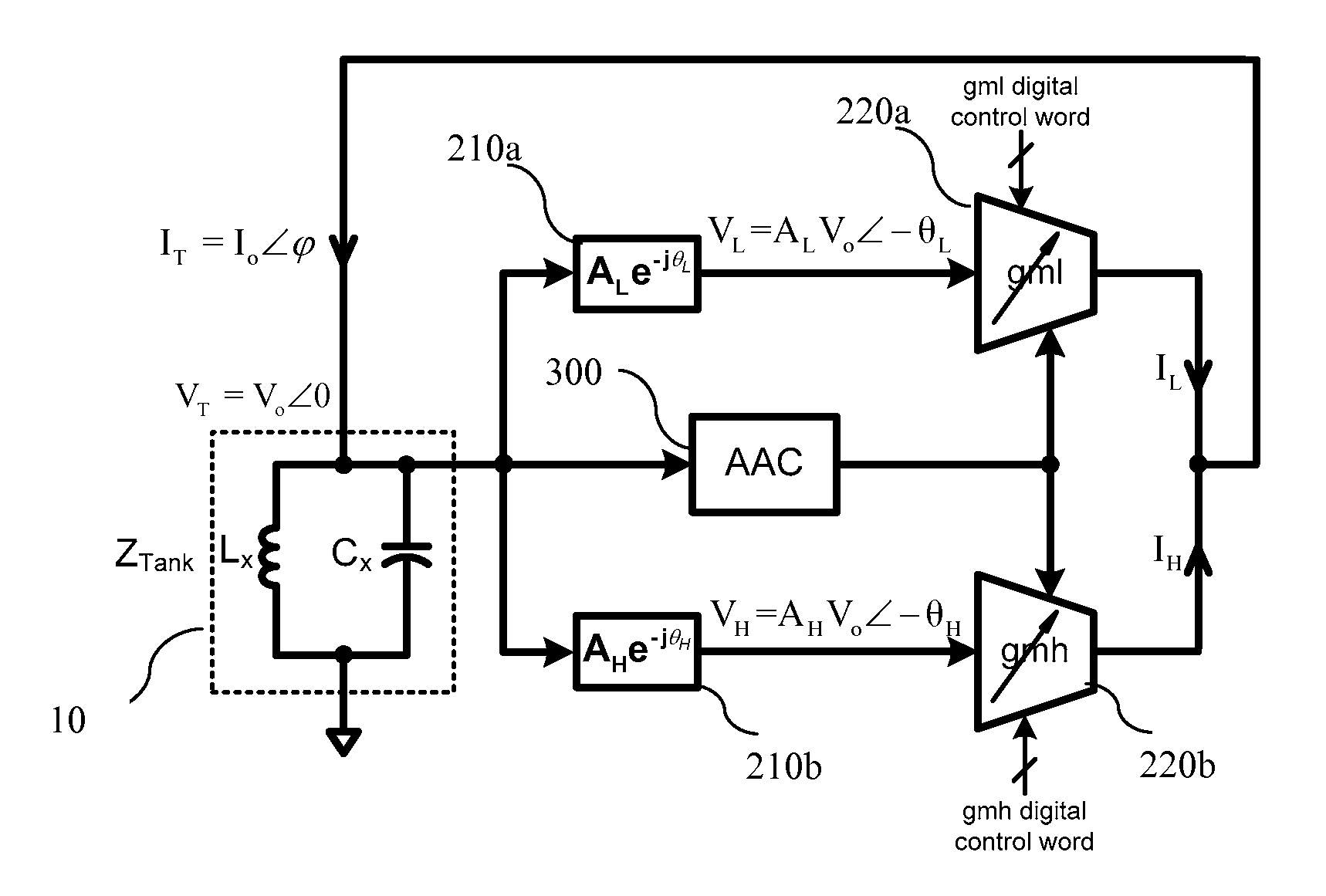
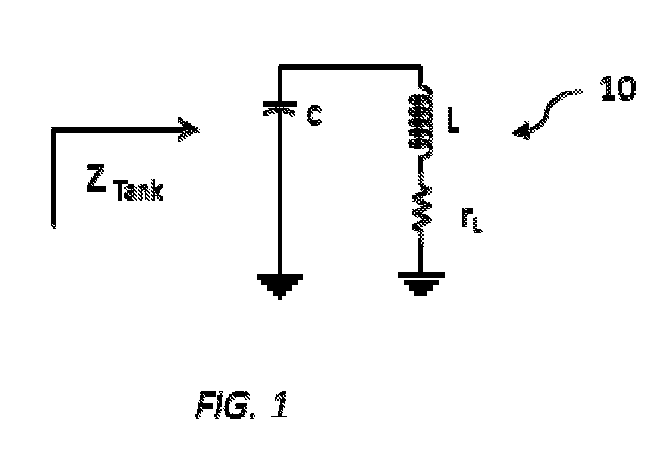
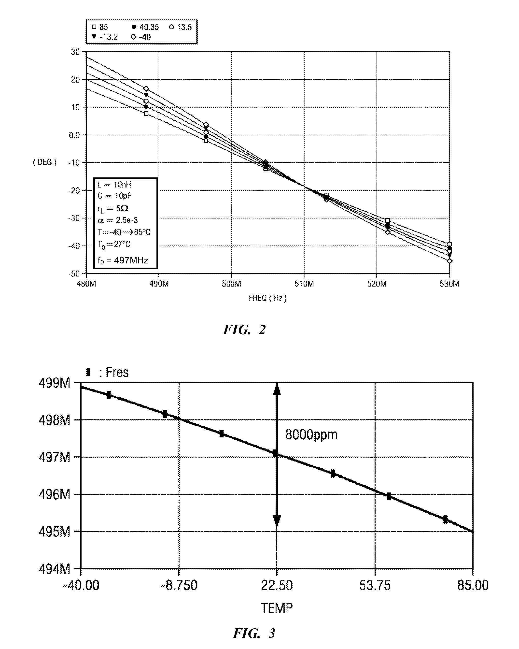
[0019]The present invention provides a substantially temperature-independent LC-based oscillator. The oscillator includes an LC oscillator tank and frequency stabilizer circuitry coupled to the LC oscillator tank to cause the LC oscillator tank to operate at a temperature null phase generating a tank oscillation at a phase substantially equal to a temperature null phase. The temperature null phase is a phase of the LC oscillator tank at which variations in frequency of an output oscillation of the oscillator with temperature changes are reduced or minimized.
[0020]For example, the feedback loop may split the output voltage of the LC tank into two voltages having different phases, where each voltage is independently transformed into a current through programmable transconductors. The two currents may be combined to form a resultant current which is then applied to the LC tank. The phase of the resultant current is adjusted such that the LC tank operates at an impedance co...
PUM
 Abstract
Description
Claims
Application Information