Optical pickup

a technology of optical pickups and optical pickups, applied in the direction of data recording, instruments, disposition/mounting of heads, etc., can solve the problems of degrading the stability of the instability of the characteristics of the actuator, and the difficulty in achieving the stability of the actuator's characteristics, so as to improve the read and write performance of the optical pickup, improve the durability of the actuator, and improve the stability of the performance

Inactive Publication Date: 2008-08-12
FUNAI ELECTRIC CO LTD
View PDF8 Cites 2 Cited by
  • Summary
  • Abstract
  • Description
  • Claims
  • Application Information

AI Technical Summary

Benefits of technology

[0022]According to the invention, the configuration described in FIG. 4 is used as a basic configuration. Then, a columnar section is added to the portion for the formation of the spaces in the fixed side support member, and the spaces are combined into one while partitions are added. When merely such simple measures are taken, the variation is suppressed in the front surface shape of the damper material filling the space so that the effective length of a plurality of the wires becomes as identical as possible. This suppresses the variation in the primary resonance frequency and in the DC sensitivity caused by the difference in the spring constant in each wire, and hence improves the stability in the read and write performance of the optical pickup.
[0023]Further, when the groove shaped cavity which forms the space is divided into the chambers by the partitions, the damper gel material filling the space engages with the partitions so that an anchor effect is obtained. This avoids the possibility of occurrence of a defective such as drop off of a damper material from the space, and hence improves the durability of the actuator and the stability in the performance.

Problems solved by technology

This causes difficulty in achieving stability in the characteristics required in the actuator 1.
This causes a variation in the primary resonance frequency of the wires 6 or in the so-called DC sensitivity, and hence causes instability in the characteristics of the actuator 1.
This can degrade the stability in the read and write performance of the optical pickup.
Thus, this technique is hardly applicable to the prior art example of the actuator 1 described in FIG. 4 where the damper material 8 is caused to fill the space 7 provided in the fixed side support member 2.
Even if applicable, the technique cannot avoid the variation in the surface shape of the front surface 81 of the damper material 8.
This causes the necessity of an extra step of applying the adhesive before the process of filling the elastic gel material, and hence increases complexity in the work.

Method used


Image

  • Optical pickup
  • Optical pickup
  • Optical pickup

Examples


Embodiment Construction

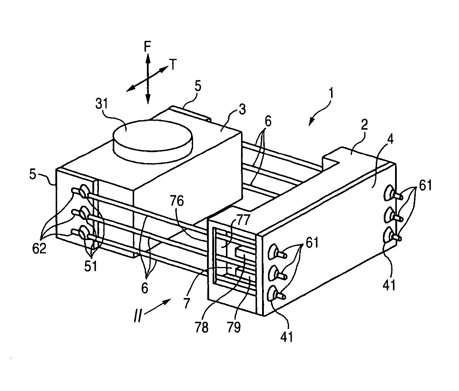
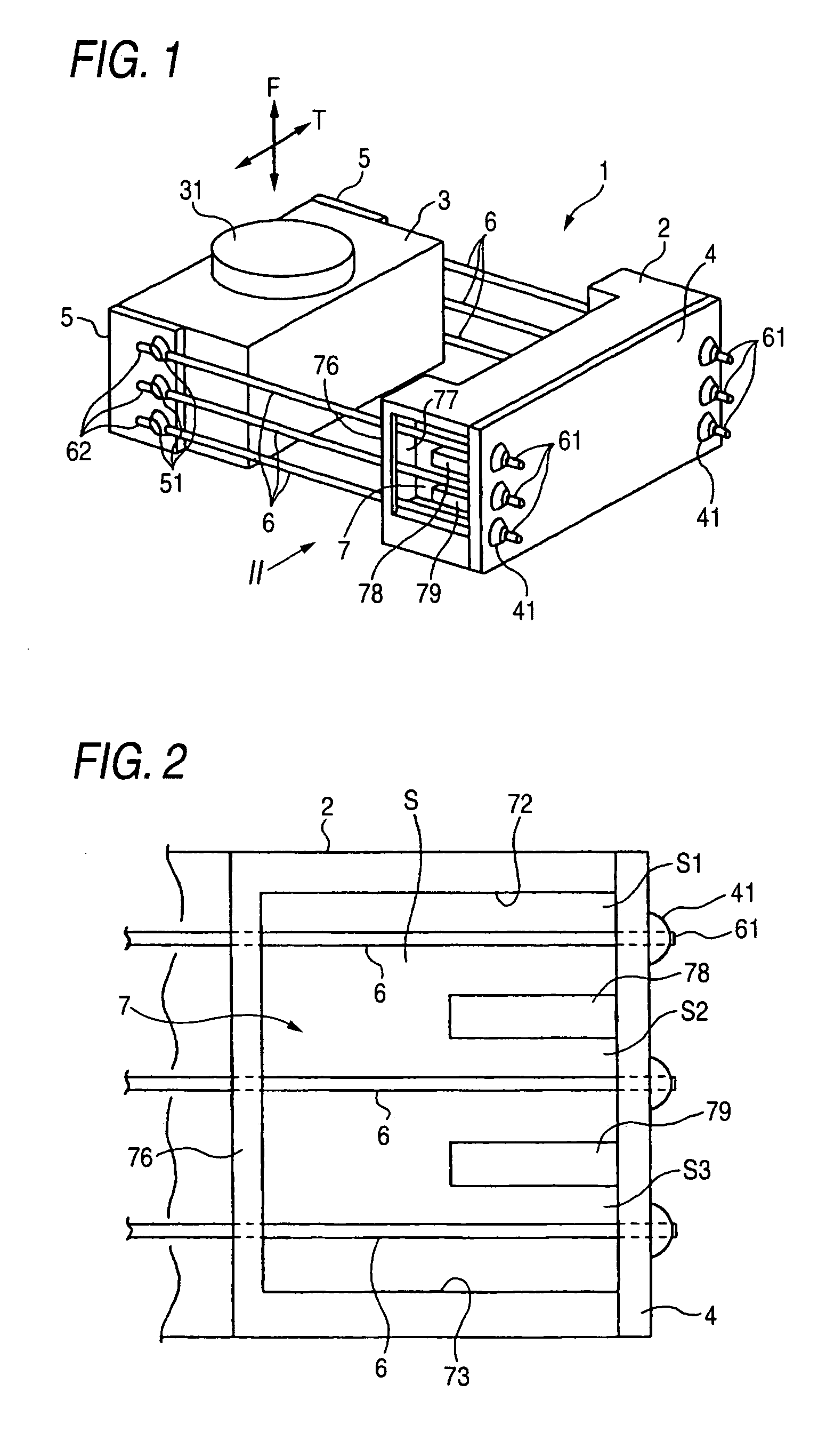
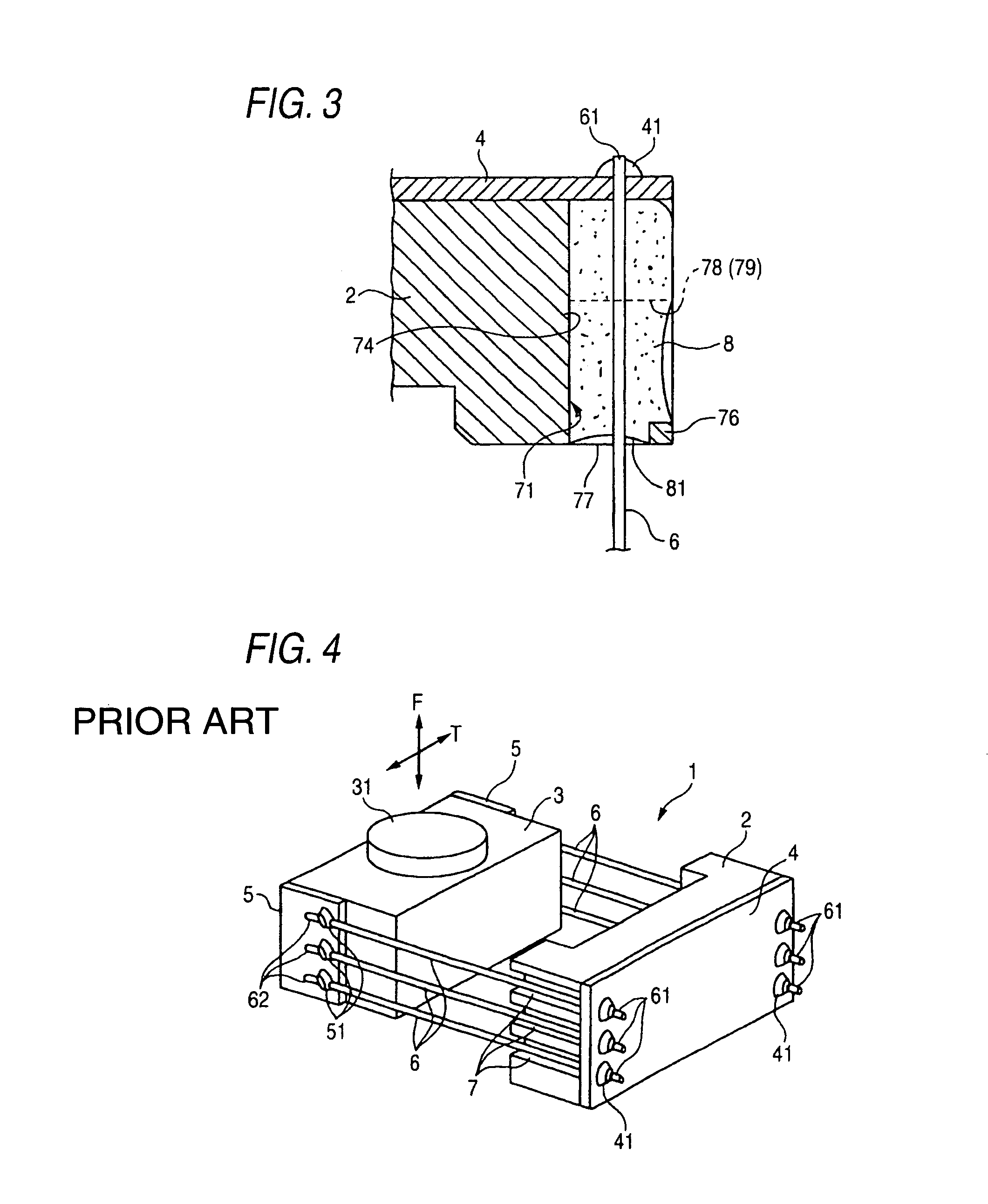
[0030]FIG. 1 is a schematic perspective view of an actuator 1 adopted in an optical pickup according to the invention. FIG. 2 is an enlarged side view of the main part of an actuator 1 viewed from the II direction of FIG. 1. FIG. 3 is an enlarged horizontal sectional plan view showing the main part of a fixed side support member 2.

[0031]In the actuator 1 of FIG. 1, the difference from the actuator 1 described in FIG. 4 is only the configuration of a space 7 formed in each of both side faces located in the right and the left direction of the fixed side support member 2. The other points are the same as those described in FIG. 4. That is, also in the present embodiment, the fixed side support member 2 of the actuator 1 is mounted on a base (not shown) driven and thereby traveling in a radial direction of a disk. Further, a movable side lens holder 3 is provided with a plurality of coils (not shown) for generating a biasing force in a focusing direction F or a tracking direction T. The...


PUM

PropertyMeasurementUnit
opticalaaaaaaaaaa
elasticaaaaaaaaaa
surface deflectionaaaaaaaaaa

Abstract

Wires are inserted through a layer of a damper material filling a space provided in a fixed side support member. The space is formed by a groove shaped cavity, while the front part of the groove shaped cavity is provided with an opening surrounded by a groove shaped surface and a columnar section. The damper material filling the space contacts closely with the groove shaped surface and the columnar section within an opening.

Description

BACKGROUND OF THE INVENTION[0001]1. Field of the Invention[0002]The present invention relates to an optical pickup installed in an optical disk drive and, in particular, to an optical pickup including an actuator in which a movable side lens holder provided with an objective lens is supported in a displaceable manner in a cantilever state by elastic wires extending from a fixed side support member.[0003]2. Description of the Related Art[0004]An optical pickup installed in an optical disk drive is used for focusing laser light on a disk surface serving as a recording medium and thereby for writing and reading data. Such an optical pickup has the function of adjusting the position of the objective lens in the focusing direction or the tracking direction in response to surface deflection and off-centering during the rotation of the disk.[0005]FIG. 4 schematically shows an actuator 1 adopted in a prior art optical pickup. The actuator 1 of the figure is mounted on a base (not shown) dri...

Claims


Application Information

Patent Timeline
Patent Type & Authority Patents(United States)
IPC IPC(8): G11B7/00G11B7/09G11B7/085
CPCG11B7/08582G11B7/0932
Inventor NOGAMI, TOYOSHI
Owner FUNAI ELECTRIC CO LTD
Why Eureka
Try Eureka