Printing quality inspection apparatus

a quality inspection and printing technology, applied in the direction of optical radiation measurement, visual presentation using printers, instruments, etc., can solve the problems of wasting printing materials, defective printing products being shipped without being detected, and heavy burden on the operator

Inactive Publication Date: 2014-08-19
KOMORI CORP
View PDF16 Cites 5 Cited by
  • Summary
  • Abstract
  • Description
  • Claims
  • Application Information

AI Technical Summary

Benefits of technology

[0007]It is an object of the present invention to provide a printing quality inspection apparatus which can inspect the printing quality of an image printed on opaque paper, vapor deposition paper, or a transparent film with the same configuration.
[0008]It is another object of the present invention to provide a printing quality inspection apparatus which reduces the manufacturing cost and prevents the waste of printing materials while relieving the operator's burden.

Problems solved by technology

Therefore, a heavy burden is inflicted on the operator.
Also, when a printing failure occurs in a printing product which is not extracted as a sample, a defective printing product is shipped without being detected.
Moreover, even if the operator becomes aware of a printing failure, defective printing products are produced in large quantities, thus wasting printing materials.
In the conventional printing quality inspection apparatus disclosed in literature 1, two types of light sources: dark- and bright-field light sources are necessary, thus leading to an increase in cost.
Also, it is necessary to operate a switch for switching the process involved, in accordance with whether a printing product printed on opaque paper or that printed on vapor deposition paper is to be inspected, thus inflicting a heavy burden on the operator.
Furthermore, if the operator is unaware of erroneous detection because he or she has forgotten to switch the process involved, large amounts of printing materials are wasted.
Therefore, due to a shortage of illumination light which impinges on the target surface, an image printed on transparent paper cannot reliably be detected.

Method used


Image

  • Printing quality inspection apparatus
  • Printing quality inspection apparatus
  • Printing quality inspection apparatus

Examples


Embodiment Construction

[0021]A printing quality inspection apparatus according to the first embodiment of the present invention will be described below with reference to the accompanying drawings.

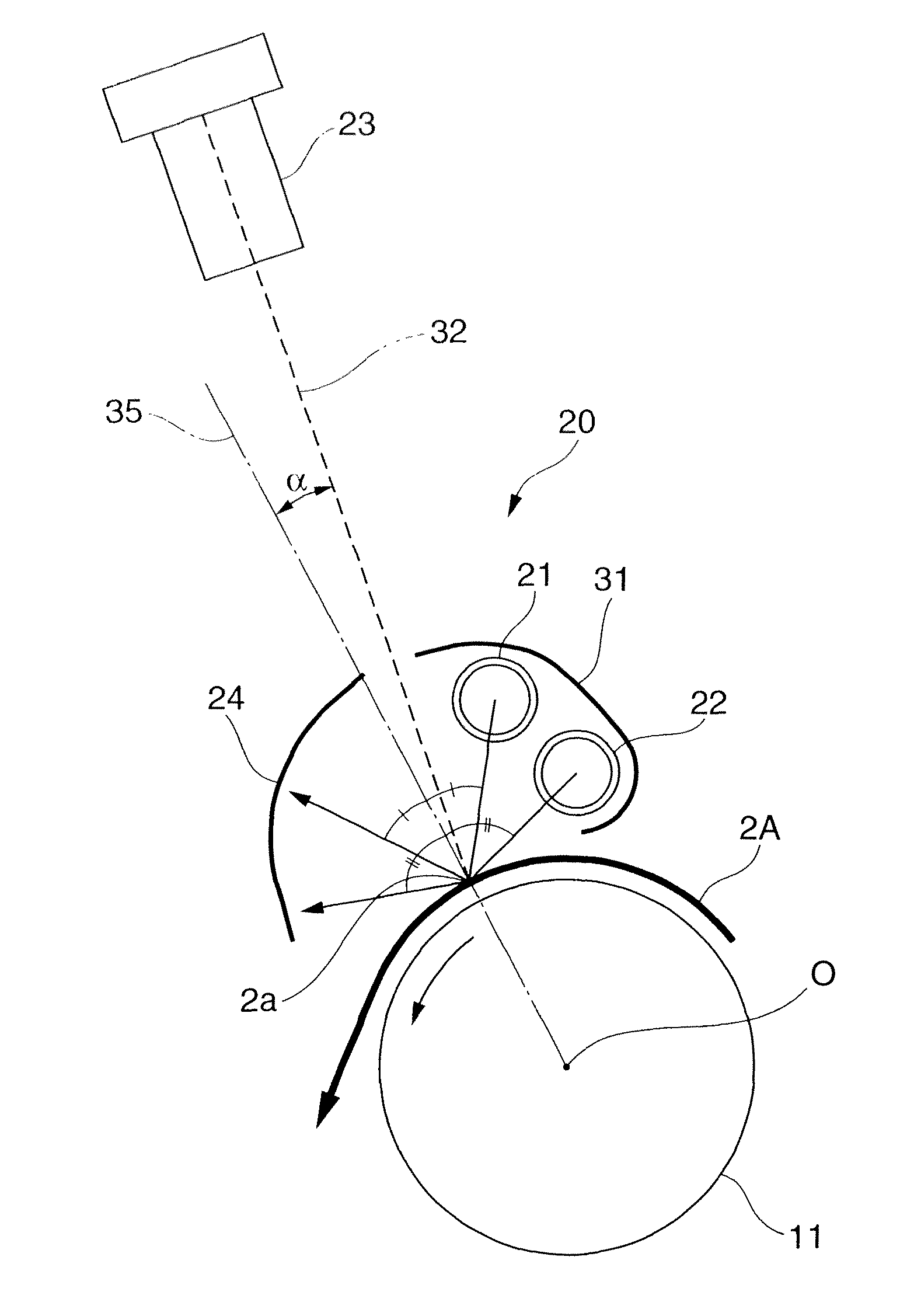
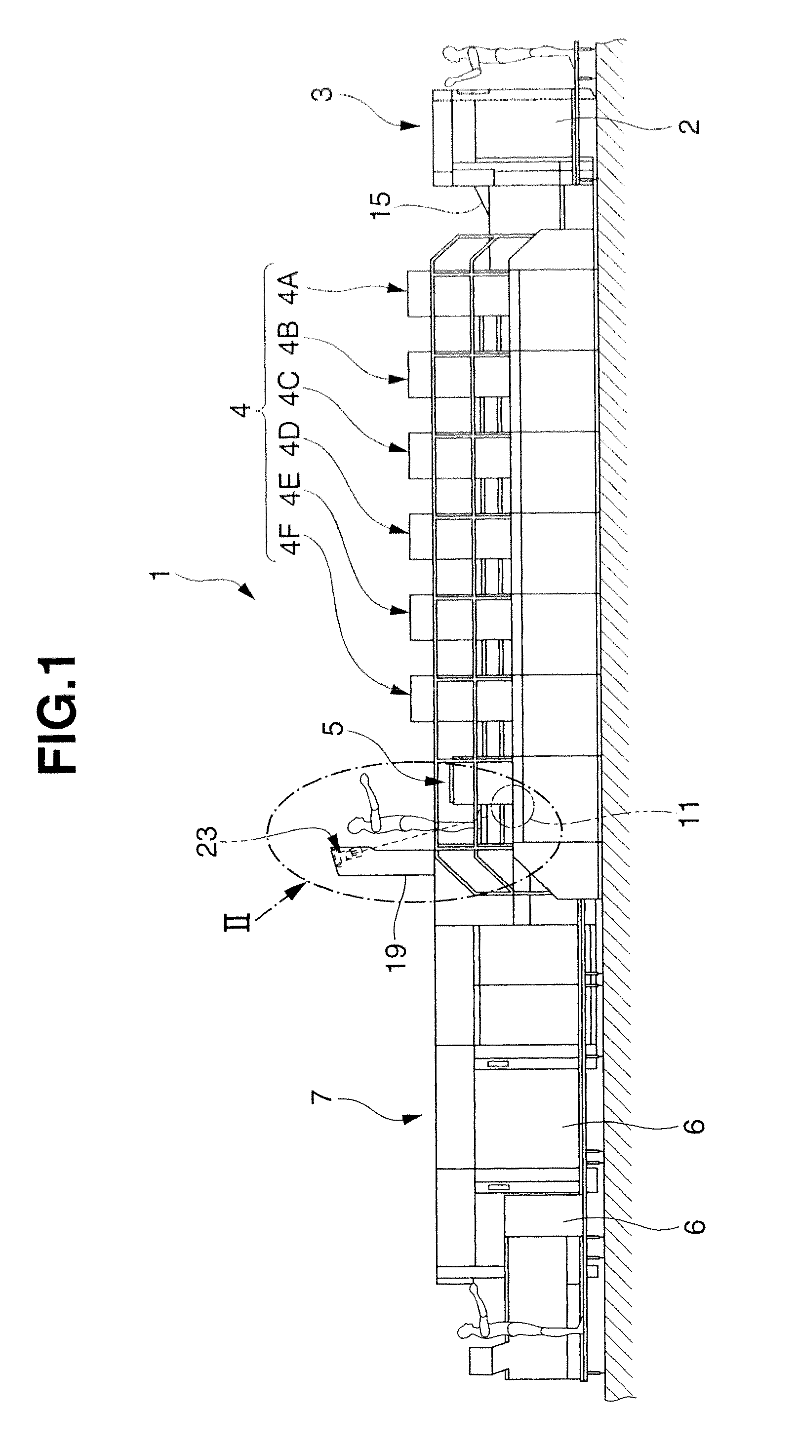
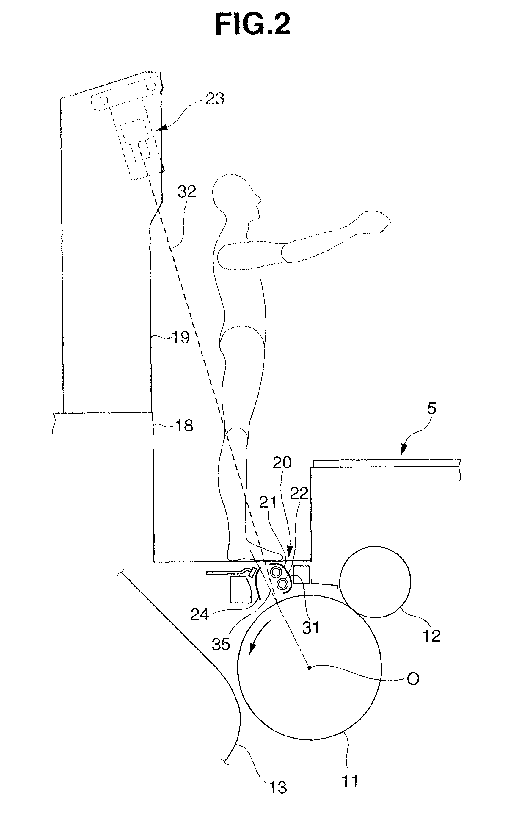
[0022]As sheet-fed offset rotary printing press 1 includes a sheet feeding device 3, printing unit 4, coating unit 5, and sheet delivery device 7, as shown in FIG. 1. The sheet feeding device 3 feeds stacked members to be printed 2 one by one. The printing unit 4 includes six printing units 4A to 4F which print six colors on the member to be printed 2 supplied from the sheet feeding device 3. The coating unit 5 coats varnish on the printing surface of the member to be printed 2 printed by the printing unit 4. The sheet delivery device 7 dries the member to be printed 2 coated by the coating unit 5, and delivers it onto a delivery pile 6.

[0023]The coating unit 5 includes an impression cylinder (transport cylinder) 11 having a nickel-chromium film (specularly reflecting film) formed on its surface by a nickel-chrom...


PUM

PropertyMeasurementUnit
transparentaaaaaaaaaa
radius of curvatureaaaaaaaaaa
translucentaaaaaaaaaa

Abstract

This invention discloses a printing quality inspection apparatus including a light irradiation device, an image capture device, a diffusely reflecting plate, and a determination device. When a member to be printed is a first sheet member, light emitted by the light irradiation device is diffusely reflected by the first sheet member and enters the image capture device. When the member to be printed is a second sheet member, the light emitted by the light irradiation device is diffusely reflected by the diffusely reflecting plate, is specularly reflected by the second sheet member, and enters the image capture device.

Description

BACKGROUND OF THE INVENTION[0001]The present invention relates to a printing quality inspection apparatus which inspects the printing quality of an image printed on opaque paper such as white paper available as a general printing sheet, vapor deposition paper having undergone a vapor deposition process on its surface, or a transparent film.[0002]In general, opaque paper such as white paper has a diffusely reflecting surface, whereas vapor deposition paper has a specularly reflecting surface. A conventional printing quality inspection apparatus which inspects whether an image printed on such opaque paper or vapor deposition paper is printed in a normal state includes two types of illumination light sources: a dark-field illumination light source and a bright-field illumination light source, as disclosed in Japanese Patent Laid-Open No. 11-108637 (literature 1). When an image of a printing product printed on an opaque printing paper sheet is to be detected by the conventional printing...

Claims


Application Information

Patent Timeline
Patent Type & Authority Patents(United States)
IPC IPC(8): G06K15/16B41F33/00G01J1/06G01J1/42G01N21/84G01N21/86G06K9/00
CPCB41F33/0036G01N21/84G01N21/86G01J1/4223G01J1/06
Inventor OHAMA, KENTARO
Owner KOMORI CORP
Why Eureka
Try Eureka