
Device that accurately measures physiological fluid flow

a technology of physiological fluid flow and measurement device, which is applied in the direction of liquid/fluent solid measurement, instruments, machines/engines, etc., can solve the problems of obstructing the catheter, affecting the patient's condition, and causing obstructing the catheter,

Active Publication Date: 2014-08-26
FUTURE PATH MEDICAL
View PDF57 Cites 28 Cited by
  • Summary
  • Abstract
  • Description
  • Claims
  • Application Information

AI Technical Summary

Benefits of technology

The present invention describes a sensor that can measure the volume of fluid in a container. The sensor has two elements that have different electrical resistances. The first element has a first resistance, while the second element has a second resistance. The second element has a third resistance, and the first element has a fourth resistance. The sensor can be designed with the same width along its length and the resistance of the elements can vary along the length of the sensor. The invention allows for the accurate sensing of fluid volumes in containers.

Problems solved by technology

Further, if there is blood in the urine, blood clots can form that may obstruct the catheter.
Both a filled bag and blocked tube can cause urine backup and a backup could cause deleterious effect on the patient's condition.
For example, there is a lack of accuracy in obtaining measurement readings that are made using the printed indicia and there is often a degree of difficulty in reading these devices depending on where they are positioned.
This is often difficult to do.
If the patient's room is dark a light must be turned on, disturbing the patient, and also disturbing their roommate in a double room.
Aside from the fact that many of these devices lack a certain degree of accuracy, they often present problems dealing with safety, high cost to manufacture and / or to operate, lack of portability, and general difficulty of use.
Many of these systems are often rendered inaccurate due to the influence of patient movement on the measuring or weighing device used within the system.
These professional systems cost several thousands of dollars.

Method used


Image

  • Device that accurately measures physiological fluid flow
  • Device that accurately measures physiological fluid flow
  • Device that accurately measures physiological fluid flow

Examples


Embodiment Construction

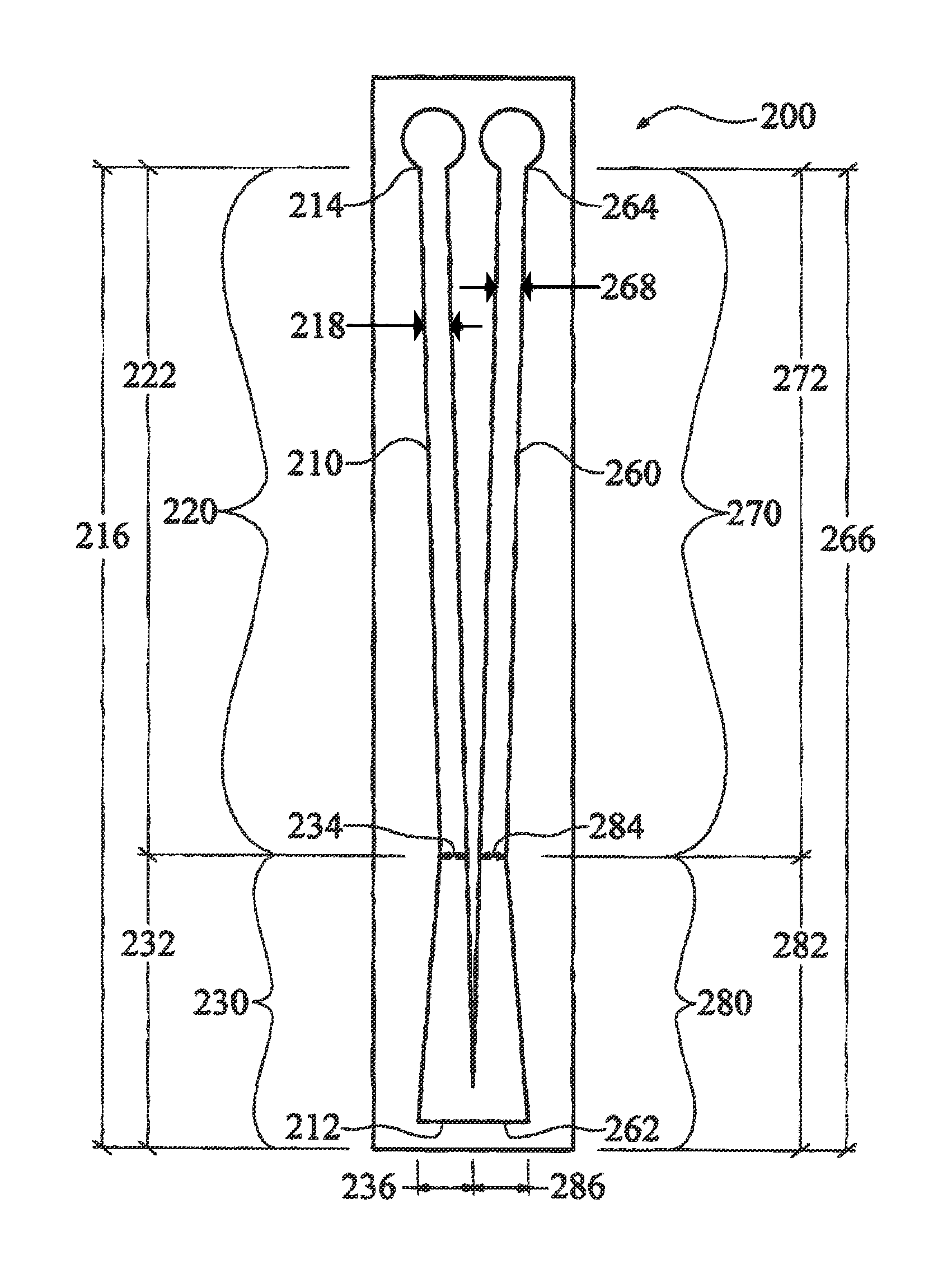
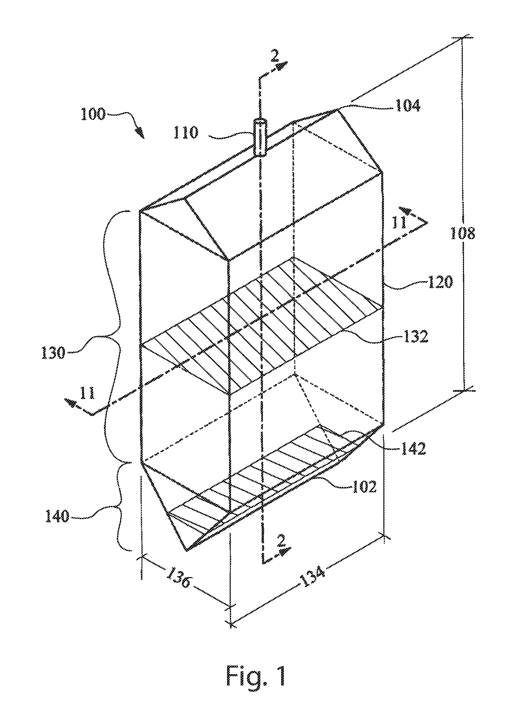
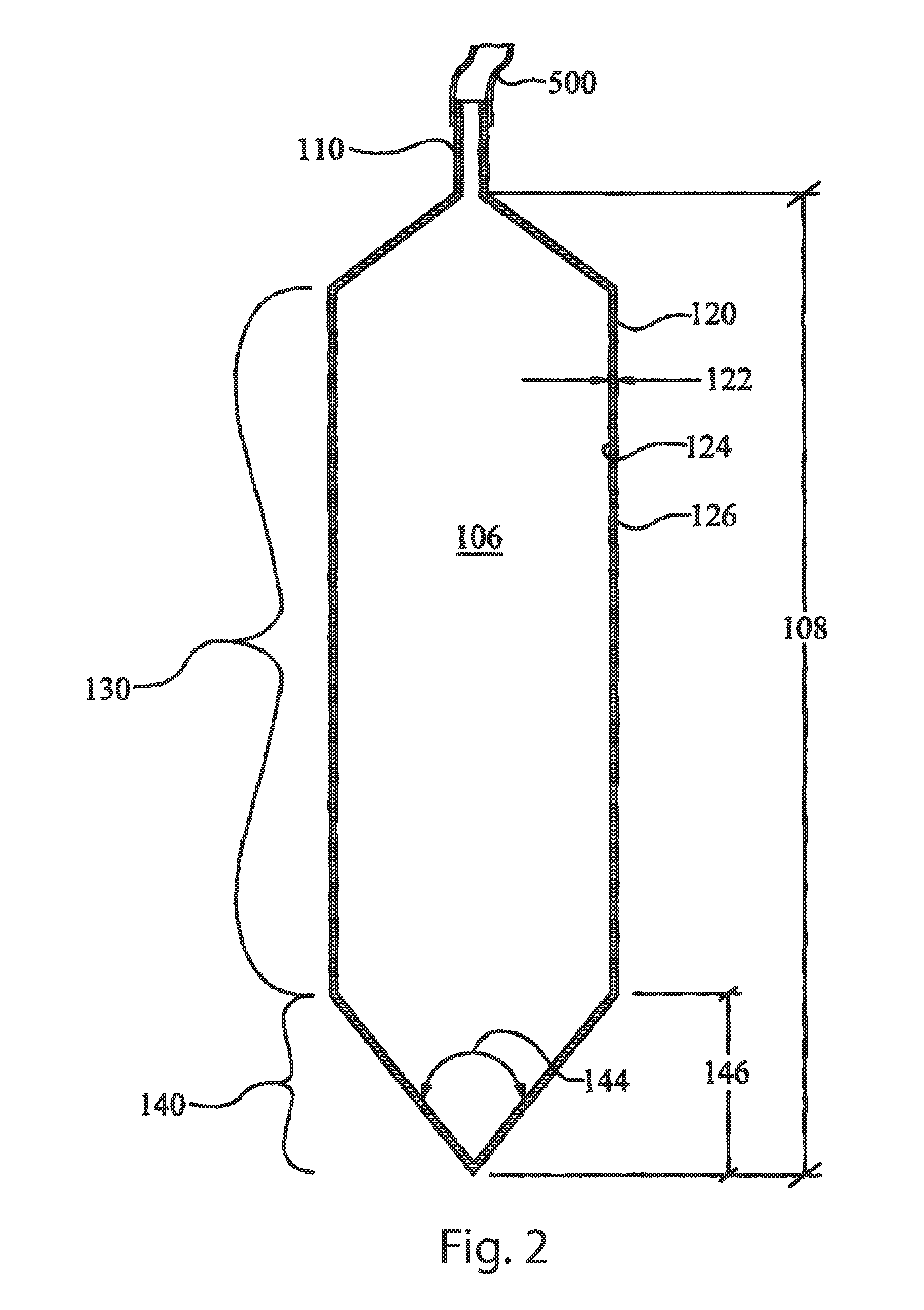
[0079]The variable cross-section containment structure liquid measurement device of the instant invention, hereafter referred to as the liquid measurement device 1, enables a significant advance in the state of the art. The preferred embodiments of the apparatus accomplish this by new and novel arrangements of elements that are configured in unique and novel ways and which demonstrate previously unavailable but preferred and desirable capabilities. The detailed description set forth below in connection with the drawings is intended merely as a description of the presently preferred embodiments of the invention, and is not intended to represent the only form in which the present invention may be constructed or utilized. The description sets forth the designs, functions, means, and methods of implementing the invention in connection with the illustrated embodiments. It is to be understood, however, that the same or equivalent functions and features may be accomplished by different emb...


PUM


Abstract

A sensor for sensing a volume of fluid in a container includes first and second elements, each element including a first portion and a second portion. The first portion of the first element has a first electrical resistance per unit length of the container and the second portion of the first element has a second electrical resistance per unit length of the container different from the first electrical resistance per unit length of the container. The first portion of the second element has a third electrical resistance per unit length of the container and the second portion of the second element has a fourth electrical resistance per unit length of the container different from the third electrical resistance per unit length of the container.

Description

RELATED APPLICATIONS[0001]This application is a continuation-in-part application of U.S. patent application Ser. No. 11 / 367,822, filed Mar. 3, 2006, now U.S. Pat. No. 7,892,217, which claims the benefit of U.S. Provisional Application No. 60 / 594,457, filed Apr. 10, 2005, as well as a continuation-in-part application of U.S. patent application Ser. No. 12 / 818,194, filed Jun. 18, 2010 now U.S. Pat. No. 8,424,376 which is a divisional application of U.S. patent application Ser. No. 11 / 947,555, now U.S. Pat. No. 7,739,907, filed Nov. 29, 2007, which claims the benefit of U.S. Provisional Appln. No. 60 / 861,632, filed Nov. 29, 2006, all of which are incorporated by reference herein in their entirety.TECHNICAL FIELD[0002]The present invention generally relates to a fluid measurement systems, especially resistance based measurement systems having variable electrical resistance sections to account for variable cross-section regions of the reservoir, or containment device.BACKGROUND OF THE IN...

Claims


Application Information

Patent Timeline
Patent Type & Authority Patents(United States)
IPC IPC(8): G01F17/00G01F23/24
CPCG01F23/242A61F5/4404A61M1/0019A61M5/1723A61M2205/3389G01F23/24A61M1/69
Inventor BOIARSKI, ANTHONY, A.
Owner FUTURE PATH MEDICAL
Learn More