Device for treating intervertebral disc herniations

a technology of disc anthroplasty and disc herniation, which is applied in the field of distraction disc anthroplasty device and method for treating intervertebral disc herniation, can solve the problems of ignoring several procedural variables, major source of back pain, pain and numbness in the leg, feet and arms of affected patients, and the use of prior art devices, so as to distract the cavity space, short-term recovery, and source of back pain

Inactive Publication Date: 2005-03-03
PMT
View PDF16 Cites 24 Cited by
  • Summary
  • Abstract
  • Description
  • Claims
  • Application Information

AI Technical Summary

Benefits of technology

[0010] It is an object of the present invention to provide an inflatable balloon device which is temporarily positioned into the treated cavity of an interveterbral disc. The balloon member may be inflated and expanded by injecting a fluid into the balloon, for example, a normal saline solution. A fill tube, connected to the valve body, is provided to permit the balloon to be filled with the fluid. When the balloon member is inflated, it occupies and distracts the cavity volume of the disc which allows the expanded balloon member to carry the loads of the vertebra and minimizes the compression on the healing annulus and nucleus due to vertebral motion or compressive bulging of the inflated balloon. By not disturbing the healing tissue, the healing process may proceed more swiftly.
[0015] An object of the present invention is to provide a balloon device for treating intervertebral disc herniations, known as a major source of back pain. It is an object of the invention to provide a balloon device which can be inserted using a minimally invasive procedure and which allows for short-term recovery from surgery and the patient's early return to normal activity. It is a further object of this invention to provide a balloon device which distracts the cavity space by providing a constant pressure and thus minimizing the compression of the healing annulus and nucleus. It is a further object of this invention to provide a balloon device which can be easily located during surgery for either insertion, expansion or removal the device.
[0016] Another object of the invention is to improve visualization of the balloon assembly during insertion, expansion and removal from the intervertebral disc space. A further object of the invention is to promote tissue ingrowth in the intervertebral disc space.

Problems solved by technology

Intervertebral disc herniations are a major source of back pain.
Herniations and ruptures of intervertebral discs may also cause pain and numbness in the leg, feet and arms of affected patients.
Pulp from the nucleus extrudes through the herniated area in the annulus producing pressure on the spinal column and / or adjacent nerves and thereby causing pain.
The use of these prior art devices do not account for several procedural variables, for example, a patient's intervertebral spacing, vacated nucleus volume, variability in spacer volume, or mismatch of spacer size to the patient.
The prior art methods also typically involve invasive surgery which require relatively long recovery times for the patient.

Method used


Image

  • Device for treating intervertebral disc herniations
  • Device for treating intervertebral disc herniations
  • Device for treating intervertebral disc herniations

Examples


embodiment 30

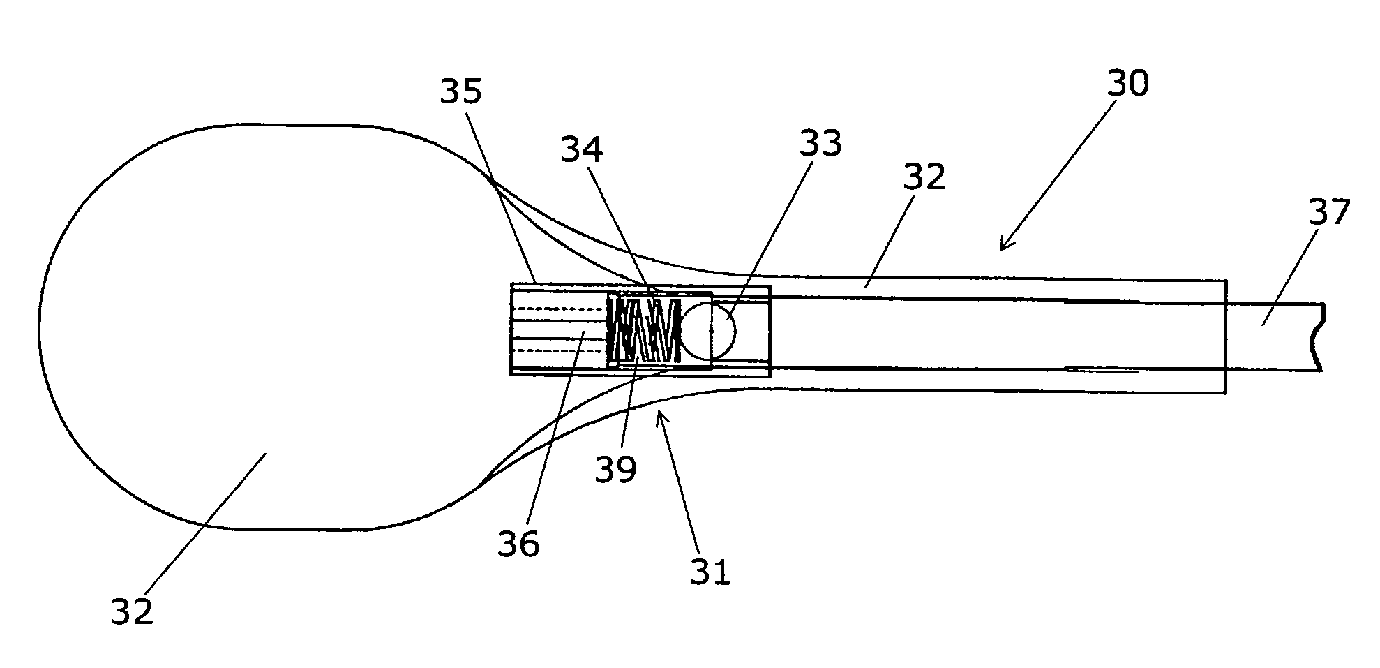
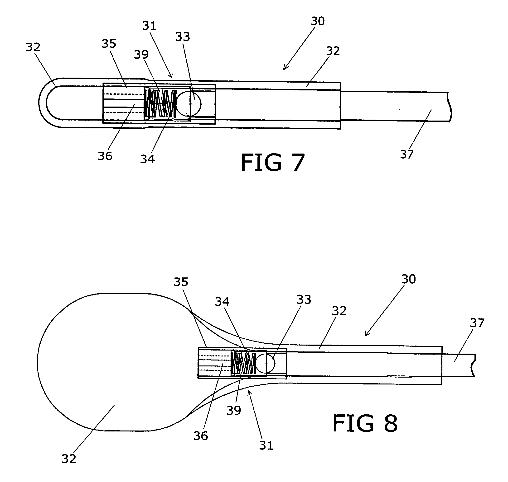
[0038] As shown in FIG. 7, the inflatable balloon device embodiment 30 of the invention comprises a rigid body portion 31 and a flexible balloon member 32. The rigid body portion 31 is shown having a valve chamber 39 containing a ball valve member 33, a biasing spring member 34, and a valve plug portion 35 positioned at one end. The valve plug portion 35 is shown having slots 36, which are constructed and arranged to allow the passage of fluid. A fill tube 37 is shown extending from the opposite end of rigid body portion 31 and is constructed and arranged to provide fluid flow through the valve plug 35 in order to inflate and deflate the balloon member 32. The ball valve member 33 is constructed and arranged to seal the fill tube 37 due to the pressure created from the spring 34 and internal pressure of the balloon member 32. FIG. 8 shows the balloon member 32 in an inflated state. In the inflated or expanded state, the balloon member 32 is shown separated from a portion of the valv...

embodiment 40

[0039] As shown in FIGS. 9 and 10, an alternate valve body embodiment 40 is shown having a valve body structure 41 having opposing ends 42 and 43. The valve body 41 has a valve chamber 44, which begins at the internally sloped valve seat 45. FIGS. 11 and 12 show valve end plug 46 which is shown inserted in end 42 of the valve body 41. The end plug 46 has a plurality of slots or channels 47 which permits the passage of fluid as described above. The end plug may be threaded into or otherwise secured in the end of the valve body 41. Although the slots or channels 47 are shown peripherally located on the end plug 46, the channels may extend through the end plug body.

[0040]FIGS. 13 and 14 show the assembled valve body 50 having ball valve 33 located in the sloped valve seat 45 and the biasing spring member 34 positioned between the end plug 46 and the ball valve 33. In a similar manner, as described above, the fill tube 37 is inserted and secured in the end portion 43 of the valve body 4...


PUM

PropertyMeasurementUnit
diameteraaaaaaaaaa
diameteraaaaaaaaaa
internal diameteraaaaaaaaaa

Abstract

A method and device for treating human intervertebral disc herniations using an endoscopic procedure. An access port is opened into and through the annulus of a disc to remove nucleus pulposus. Subsequent treatment, a balloon device having a valve structure is positioned via an endoscopic procedure into the disc space. The balloon device is filled with a physiological fluid to occupy the disc interspace or to maintain some degree of distraction of the created disc space. Post surgery, after fibrocollagenous tissue has grown into the disc space, a second endoscopic procedure is performed to remove the balloon device. Fluid is removed to collapse the balloon structure and then removed via the guide tube. The ingrowth of fibrocollagenous tissue will continue to fill the void formerly occupied by the balloon device. The balloon device has a rigid valve body and a flexible balloon member. The valve body has an end plug, a valve chamber holding a valve member and a cooperating biasing structure. The balloon member of the device is inserted into a vacated nucleus space of a herniated disc and then inflated with a physiological fluid using a fill tube. The balloon member, valve body, and fill tube or portions thereof may be constructed of a radiolucent material to provide visibility during implantation, surveillance and removal. The balloon device may be used in the cervical, lumbar or thoracic region of the spine.

Description

[0001] This application is a continuation-in-part of co-pending U.S. Patent Application entitled “Method and Device for Treating Intervertebral Disc Herniations”, having Ser. No. 10 / 147,580 and filed on May 16, 2002. The '580 Patent application is fully incorporated by reference herein.BACKGROUND OF THE INVENTION [0002] The present invention relates generally to a method and device for treating intervertebral disc herniations using an endoscopic procedure. Particularly, this invention relates to a distraction disc anthroplasty device and method for treating intervertebral disc herniations. More particularly, the present invention relates to treating intervertebral disc herniations using a temporary flexible balloon device in the treated disc to alleviate pressure between adjacent vertebrae located in the cervical, thoracic, or lumber areas of the spine. [0003] Intervertebral disc herniations are a major source of back pain. Herniations and ruptures of intervertebral discs may also c...

Claims


Application Information

Patent Timeline
Patent Type & Authority Applications(United States)
IPC IPC(8): A61F2/00A61F2/02A61F2/30A61F2/44A61F2/46
CPCA61F2/441A61F2/4611A61F2002/30062A61F2002/3008A61F2250/0098A61F2002/444A61F2002/4627A61F2210/0004A61F2002/30672
Inventor SINGER, DERON J.CAILLE, ERIC F.REUTER, MERRILL W.
Owner PMT
Why Eureka
Try Eureka