Disposable device for the continuous centrifugal separation of a physiological fluid

a technology of physiological liquid and dispersion device, which is applied in the direction of centrifuges, etc., can solve the problems of affecting the separation quality, the diameter of the centrifuging bowl cannot be too small, and the rate at which the centrifuging bowl rotates is limited, so as to reduce the tolerance of this diameter, reduce the amount of shrinkage, and reduce the effect of heating

Active Publication Date: 2011-12-06
SORIN GRP ITAL SRL
View PDF54 Cites 23 Cited by
  • Summary
  • Abstract
  • Description
  • Claims
  • Application Information

AI Technical Summary

Benefits of technology

[0021]The small diameter of the cylindrical narrowing makes it possible to reduce the tolerance on this diameter by reducing the amount of shrinkage of the plastic, this degree of shrinkage being proportional to the size of the part. The fact that the rotary seal also operates on a small-diameter part means that the amount of heating can be reduced. Furthermore, the precision with which the centrifuging device is guided means that the seal can be used only for sealing rather than also for compensating for eccentricity of the rotary centrifuging chamber with respect to the fixed axial inlet and outlet element. As a result, the preload to which the seal needs to be subjected can be reduced to the minimum, that is to say that it is now dependent only on the conditions needed for sealing and therefore no longer constitutes a hybrid component, thus also making it possible to reduce the degree of heating.

Problems solved by technology

As a result, the rate at which the centrifuging bowl rotates is limited, which means that the diameter of this bowl cannot be too small otherwise separation quality will be adversely affected.
Furthermore, the mechanism used to drive the bowl and the flexible tube is relatively complicated and expensive.
Given the bell shape of these chambers, it is not possible to cause the liquid that is to be separated to flow.
It can thus be seen that the existing solutions are unable to provide a satisfactory answer to the need for a simple compact separator that is easy to use, that can be used with good-value disposable centrifuging chambers in which the blood that is to be processed resides for the shortest possible length of time and which are able to operate at a good delivery rate.

Method used


Image

  • Disposable device for the continuous centrifugal separation of a physiological fluid
  • Disposable device for the continuous centrifugal separation of a physiological fluid
  • Disposable device for the continuous centrifugal separation of a physiological fluid

Examples


Embodiment Construction

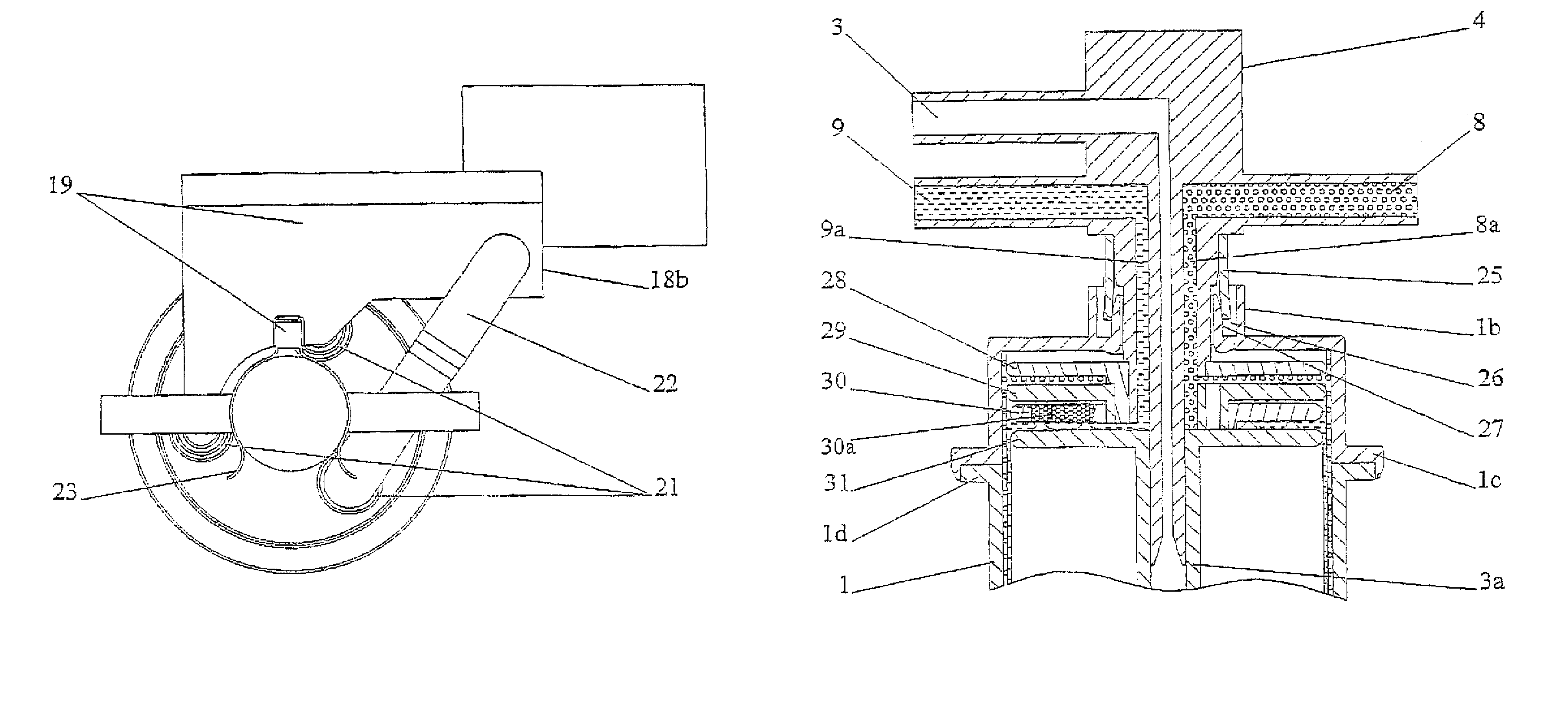
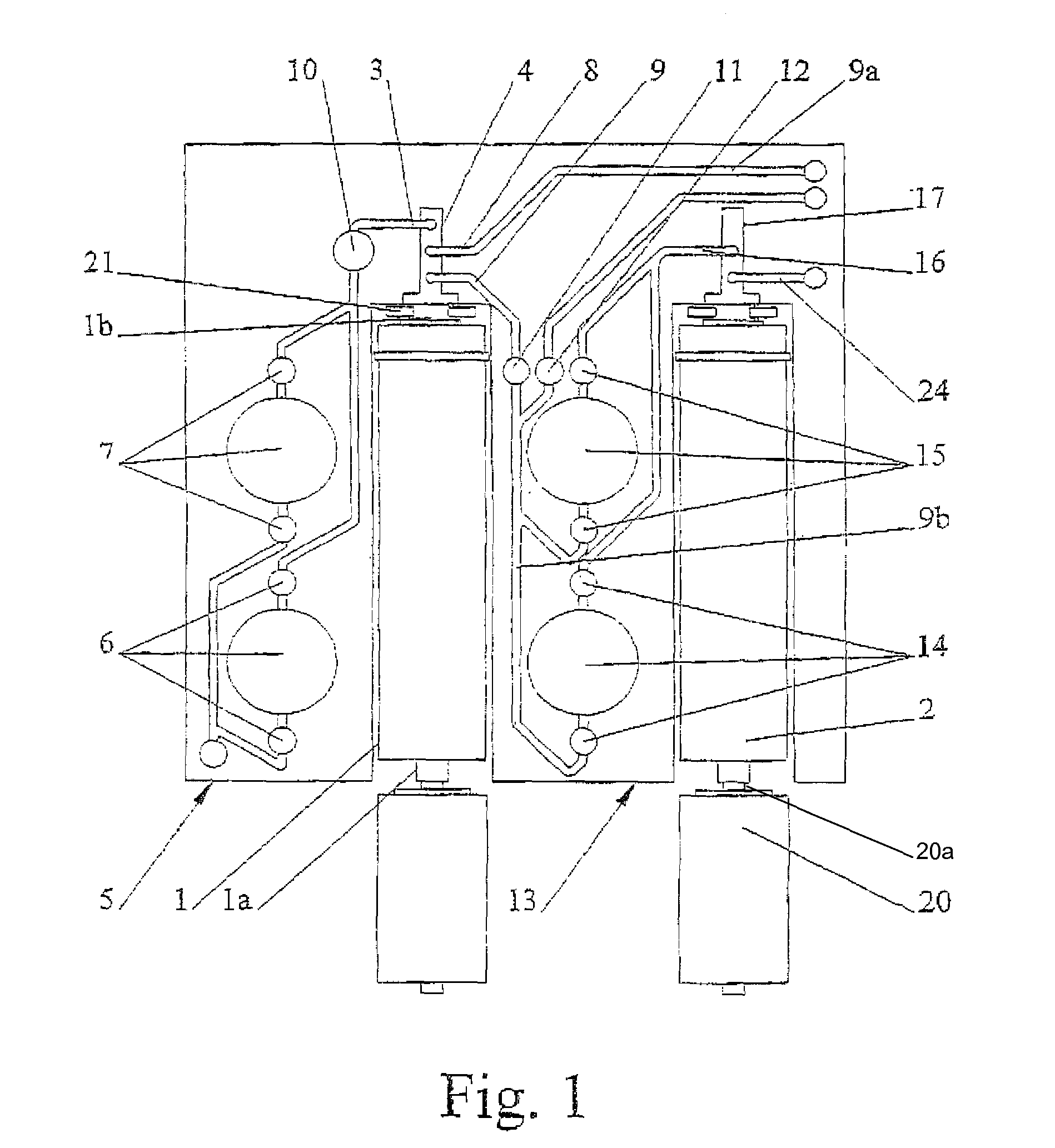
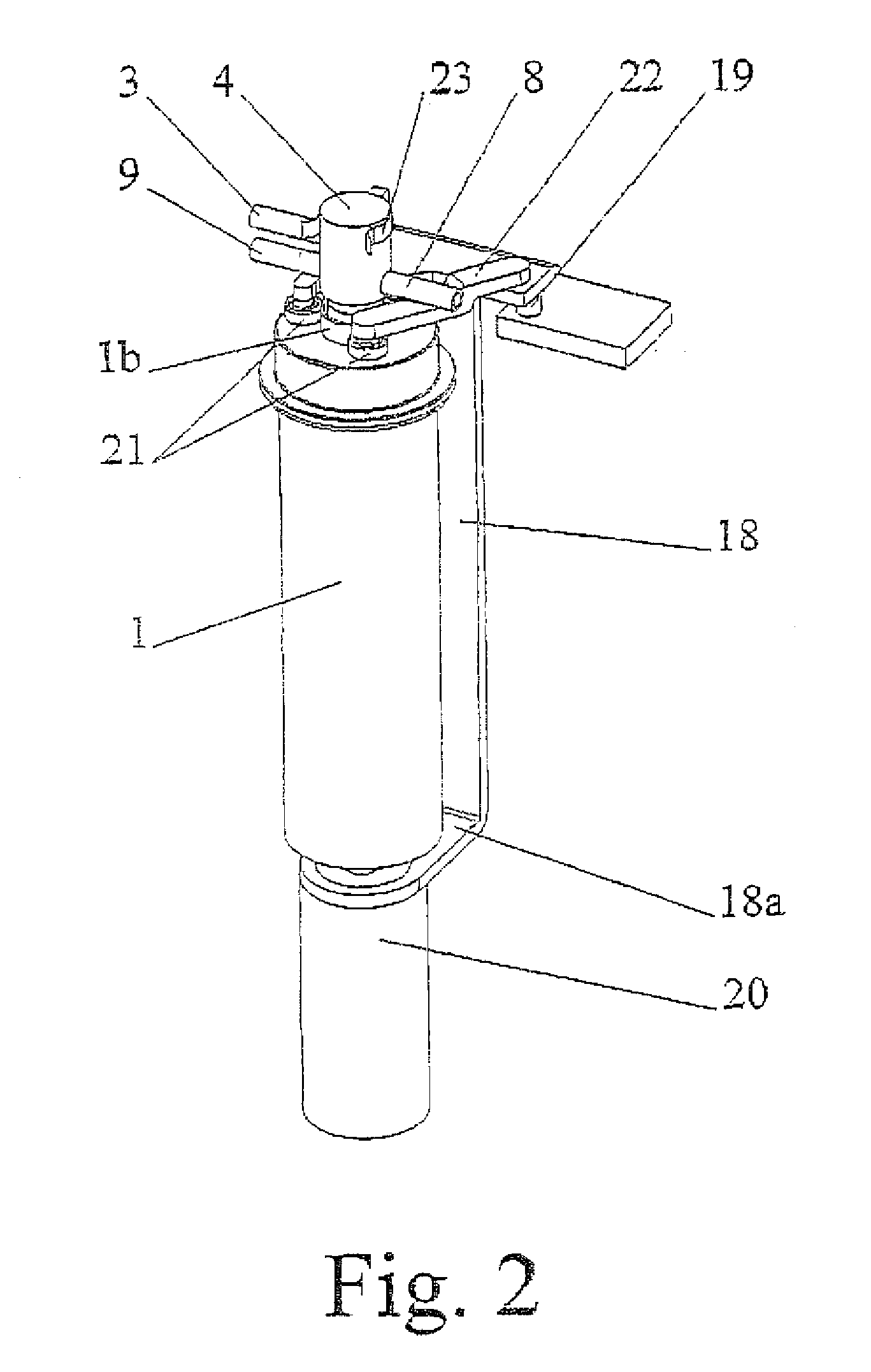
[0028]The housing of the centrifugal separator intended to use the device according to the present invention and illustrated schematically by FIG. 1 comprises two elongate centrifuging chambers 1, 2 of tubular shape. The first tubular centrifuging chamber 1 comprises a feed tube 3 which is connected to the fixed axial inlet and outlet element 4 of the centrifuging chamber 1. This feed tube 3 is connected to a pumping device 5 which comprises two pumps 6 and 7 phase-shifted from one another by 180° so as to provide a continuous flow of physiological liquid, particularly blood. An air detector 10 is positioned along the feed tube 3.

[0029]Two outlet pipes 8, 9 are connected to the fixed axial element 4 to allow the continuous delivery of two constituents that have different densities of the physiological liquid. In the case of blood, the outlet pipe 8 is intended for delivering concentrated red blood cells RBC and the pipe 9 is intended for delivering platelet rich plasma PRP. This out...


PUM


Abstract

The invention relates to disposable device for the continuous centrifugal separation of a physiological fluid. The inventive device comprises: a fixed axial element; a centrifugation chamber which is mounted such that it can rotate around the axis of said element; an inlet channel for the blood to be centrifuged, the dispensing port of which is located close to the base of the chamber; and an outlet passage for a separated constituent, the inlet port of which is located close to the other end of the chamber in a concentrated area of one of the separated constituents having the lowest mass density in order for same to be removed continuously. The above-mentioned chamber takes the form of a long tube. The fixed axial element comprises a second outlet passage for a second of the separated constituents, the inlet port of which is located close to the end of the chamber opposite the above-mentioned base in a concentrated area of said second separated constituent having the highest mass density in order for same to be removed continuously.

Description

FIELD OF THE INVENTION[0001]The present invention relates to a disposable device for the continuous centrifugal separation of a physiological liquid, particularly blood, comprising a fixed axial input and output element about the axis of which a plastic centrifuging chamber is mounted such that it can rotate, an inlet pipe for the blood that is to be spun in the centrifuge passing longitudinally through said axial inlet and outlet element, its delivery opening lying near the bottom of said centrifuging chamber, an outlet passage for at least one separated constituent, its inlet opening lying near the opposite end of said chamber to said bottom and in a region where at least one of the separated constituents that has the lowest specific mass becomes concentrated so that it can be drawn off continuously, this passage passing through a longitudinal portion of said fixed axial inlet and outlet element, a rotary seal between said fixed axial element and said centrifuging chamber.BACKGROU...

Claims


Application Information

Patent Timeline
Patent Type & Authority Patents(United States)
IPC IPC(8): B04B7/06
CPCB04B5/0442B04B5/10B04B7/00B04B9/12B04B11/082B04B2005/0478B04B2007/005
Inventor ROCHAT, JEAN-DENIS
Owner SORIN GRP ITAL SRL
Why Eureka
Try Eureka