Ion energy analyzer and methods of manufacturing the same
What is AI technical title?
AI technical title is built by Patsnap AI team. It summarizes the technical point description of the patent document.
a technology of ion energy analyzer and manufacturing method, which is applied in the field of ion energy analysis, can solve problems such as substantive nois
Inactive Publication Date: 2014-08-26
TOKYO ELECTRON LTD
View PDF42 Cites 11 Cited by
Summary
Abstract
Description
Claims
Application Information
AI Technical Summary
This helps you quickly interpret patents by identifying the three key elements:
Problems solved by technology
Method used
Benefits of technology
Problems solved by technology
For example, most known conventional analyzers perturb the processing plasma to an extent that the measurement is no longer characteristic of the conditions prevailing when processing a substrate, fail to operate at large electric potentials, and / or exhibit substantive noise arising from secondary electron emission within the analyzer.
Method used
Image
Click on the blue label to locate the original text in one second.
Reading with bidirectional positioning of images and text.
Examples
Embodiment Construction
[0043]In the following description, to facilitate a thorough understanding of the invention and for purposes of explanation and not limitation, specific details are set forth, such as a particular geometry of the plasma processing system and various descriptions of the system components. However, it should be understood that the invention may be practiced with other embodiments that depart from these specific details.
[0044]Nonetheless, it should be appreciated that, contained within the description are features which, notwithstanding the inventive nature of the general concepts being explained, are also of an inventive nature.
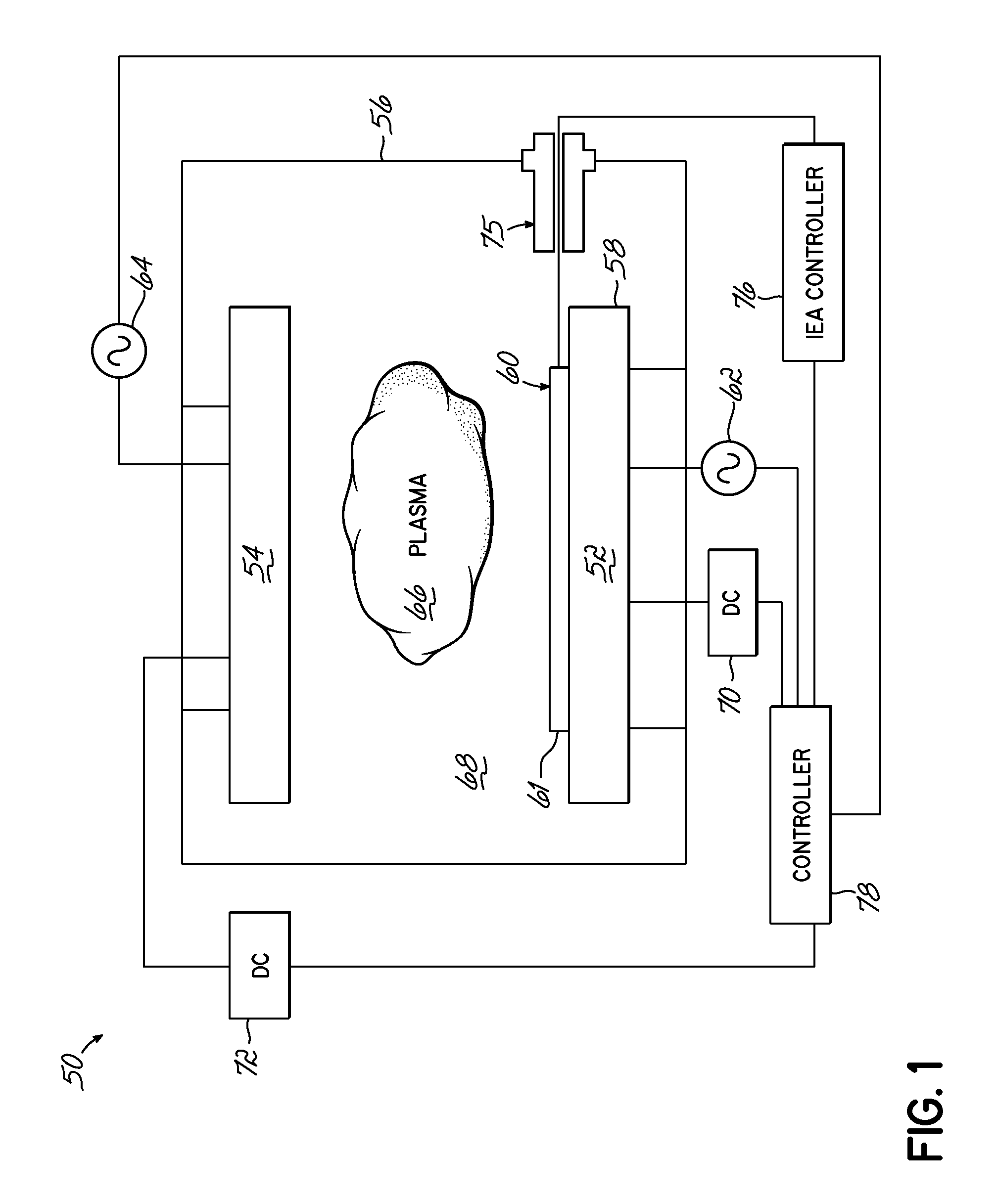
[0045]Referring now to the figures, and in particular to FIG. 1, a simplified schematic of a plasma processing system 50 according to one embodiment of the present invention is shown. The plasma processing system 50 comprises a first electrode 52 and a second electrode 54 disposed on generally opposing sides of a processing chamber 56, wherein the first electro...
PUM
Property
Measurement
Unit
temperature
aaaaa
aaaaa
DC voltage
aaaaa
aaaaa
DC voltage
aaaaa
aaaaa
Abstract
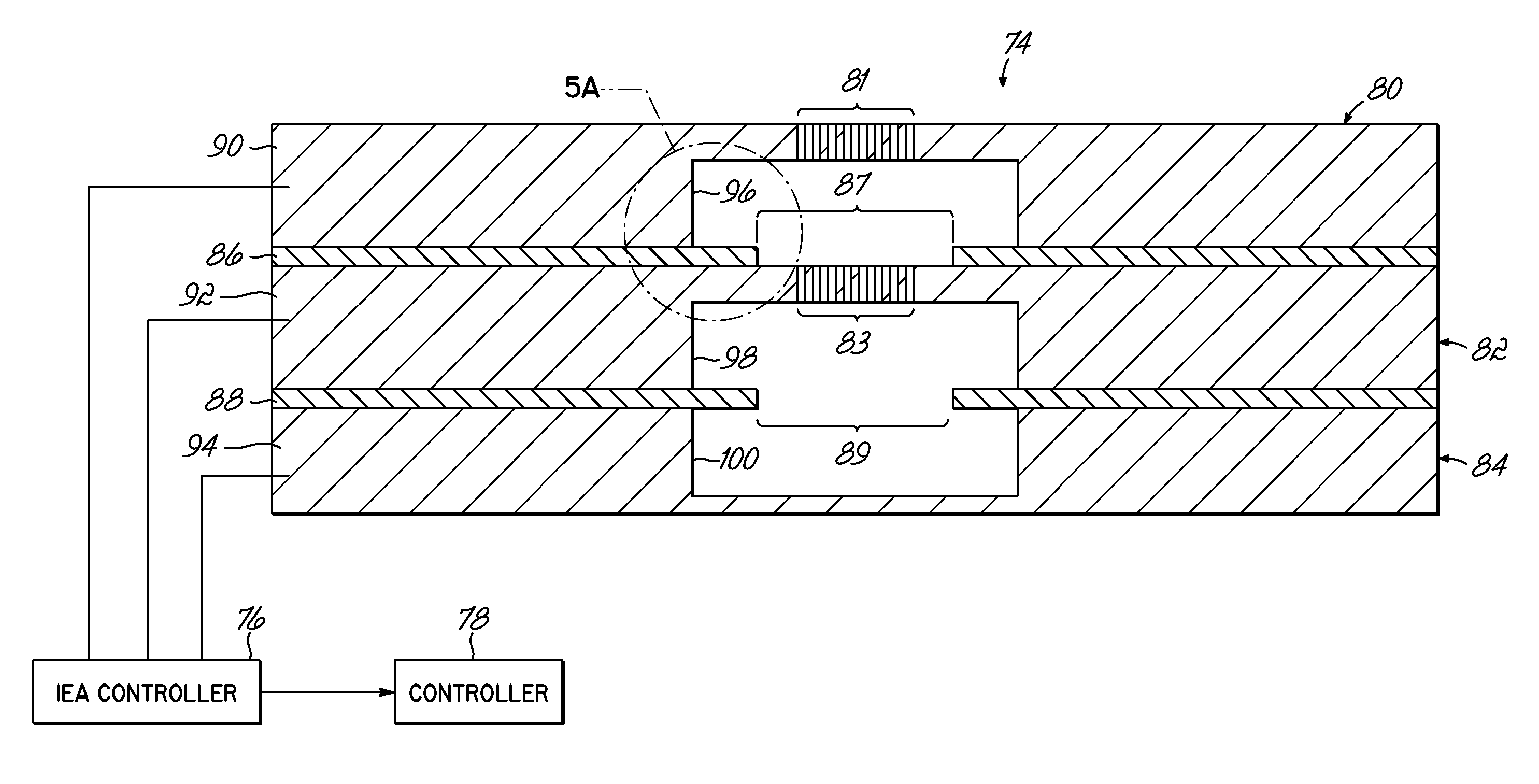
A process by which an ion energy analyzer is manufactured includes processing a first substrate to form an entrance grid having a first channel and a first plurality of openings extending therethrough. A second substrate is processed to form a selection grid having a second channel therein and a second plurality of openings extending therethrough. A third substrate is processed to form an ion collector having a third channel therein. The entrance grid is operably coupled to, and electrically isolated from, the selection grid, which is, in turn, operably coupled to, and electrically isolated from, the ion collector.
Description
[0001]The present application claims the filing benefit of U.S. Provisional Patent Application No. 61 / 468,187, filed on Mar. 28, 2011, the disclosure of which is hereby incorporated by reference herein in its entirety. The present application is related to co-pending U.S. application Ser. No. 13 / 433,071, entitled ION ENERGY ANALYZER; U.S. application Ser. No. 13 / 433,078, entitled METHODS OF ELECTRICAL SIGNALING IN AN ION ENERGY ANALYZER; and International Application Serial No. PCT / US2012 / 030960, entitled ION ENERGY ANALYZER, METHODS OF ELECTRICAL SIGNALING THEREIN, AND METHODS OF MANUFACTURING AND OPERATING THE SAME. These related, co-pending applications were filed on even date herewith and the disclosure of each is incorporated herein by reference, in its entirety. The present application is also related to commonly assigned U.S. Pat. No. 7,777,179, issued on Aug. 17, 2010, and U.S. Pat. No. 7,875,859, issued on Jan. 25, 2011, the disclosures of which are also hereby incorporated...
Claims
Application Information
Patent Timeline
Application Date:The date an application was filed.
Publication Date:The date a patent or application was officially published.
First Publication Date:The earliest publication date of a patent with the same application number.
Issue Date:Publication date of the patent grant document.
PCT Entry Date:The Entry date of PCT National Phase.
Estimated Expiry Date:The statutory expiry date of a patent right according to the Patent Law, and it is the longest term of protection that the patent right can achieve without the termination of the patent right due to other reasons(Term extension factor has been taken into account ).
Invalid Date:Actual expiry date is based on effective date or publication date of legal transaction data of invalid patent.

