

Mobile station, base station, radio communication system, and communication control method
a mobile station and radio communication technology, applied in the field of radio communication system, can solve the problem that the base station cannot directly determine the amount of data stored, and achieve the effect of increasing uplink capacity
- Summary
- Abstract
- Description
- Claims
- Application Information
AI Technical Summary
Benefits of technology
Problems solved by technology
Method used
Image

Examples
Embodiment Construction
[0065]The best mode for carrying out the invention is described based on the following embodiments with reference to the accompanying drawings. Throughout the accompanying drawings, the same reference numbers are used for parts having the same functions, and overlapping descriptions of those parts are omitted.
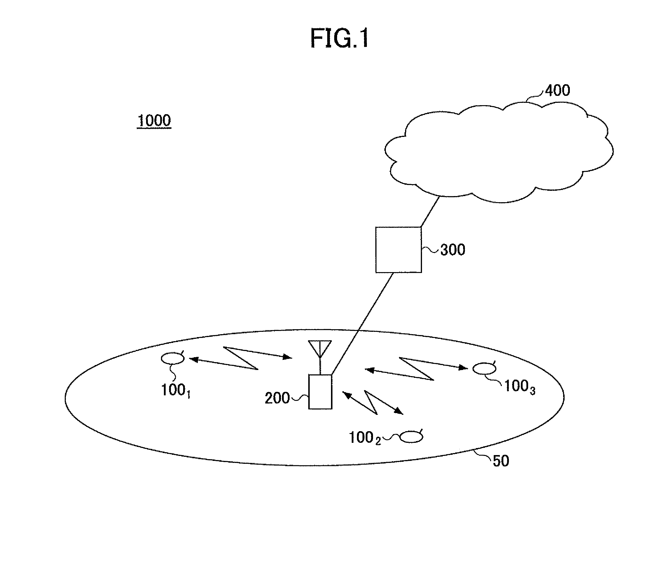
[0066]A radio communication system 1000 including mobile stations and a base station according to an embodiment of the present invention is described below with reference to FIG. 1.
[0067]The radio communication system 1000 is based on, for example, Evolved UTRA and UTRAN (also called Long Term Evolution or Super 3G). The radio communication system 1000 includes a base station (eNode B: eNB) 200 and mobile stations 100n (1001, 1002, 1003, . . . 100n; n is an integer greater than 0). The base station 200 is connected to an upper node such as an access gateway 300 and the access gateway 300 is connected to a core network 400. The mobile stations 100n are in a cell 50 and communica...
PUM
 Abstract
Description
Claims
Application Information