Supercharge Your Innovation With Domain-Expert AI Agents!

Snowmobile rear suspension

a rear suspension and snowmobile technology, applied in vehicle propulsion, vehicle components, rider propulsion, etc., can solve the problems of unsatisfactory movement type, excessive chassis pitch, and degree of uncoupled behavior in a coupled suspension

Active Publication Date: 2014-09-02
POLARIS IND INC
View PDF30 Cites 8 Cited by
  • Summary
  • Abstract
  • Description
  • Claims
  • Application Information

AI Technical Summary

Benefits of technology

The patent text describes a snowmobile suspension system that includes a frame, slide rails for mounting endless track, and a linkage between the slide rails and frame. The linkage includes a pivot link that pivots in response to movement between the slide rails and frame. The system also includes at least one linear force element (LFE) that is positioned above or outside of the endless track. The LFE is connected to the frame and the linkage, and its movement is stroked by the pivot link. The system may also include straddle links that flank the endless track. The technical effects of this system include improved snowmobile performance and stability.

Problems solved by technology

An uncoupled suspension will allow excessive chassis pitch due to the independence of the suspension.
This is not desirable because the slide rail will not follow undulating terrain or allow any angle change relative to the chassis due to acceleration.
There is always some degree of uncoupled behavior in a coupled suspension when the geometry is not locked front-to-rear or rear-to-front.
This type of movement is not desirable due to the need to achieve traction on undulating terrain.
The problem lies in packaging a four link geometry that does not move over-center during compression.
Simply moving the rear point of a conventional suspension upward is not feasible.
Ratios other than this are not feasible or do not package in current design envelopes.
This type of behavior is not ideal because as the rail angle increases, rate and damper velocities decrease ultimately resulting in a regressive suspension.
However, an increasing coupling angle is difficult to eliminate due to the packaging of a traditional snowmobile suspension.
This is very beneficial, but excessive vehicle pitch and lack of vertical rate usually make uncoupled suspensions behave poorly for load carrying capacity and ride quality.
The inherent problem is that these designs lose rate near full jounce due to the suspension mechanism components becoming generally planer.
This is due to the large vertical travel requirements of a snowmobile suspension.
Progressive rate suspensions have not yet been achieved in snowmobile rear suspension designs because 1) the vertical component of the LFE becomes very small as the LFEs become horizontal and planar with the suspension during jounce, and 2) the rotational component of the LFE about the arm pivot also cannot increase faster than the increase in arm length moment.
Some architectures yield discontinuities that may locally spike the rate for a short time (such as an overload spring), but afterwards the rate continues to decrease.
Because most design effort is directed at optimizing a damper or spring motion ratio instead of analyzing the entire suspension system there are currently no progressive rate suspensions in the industry.
This conventional suspension arrangement poses two problems.
First, track tension through suspension travel relies on the relative placement of the suspension arms and wheels to the drive shaft.
Problems are encountered from both an over and under tensioning track standpoint.
Second, the front arm placement is limited to remain outside the drive sprocket diameter due to interference with drive train components.
This creates problems when attempting to change the weight transfer behavior of the rear suspension, which is dominated by front arm mount location.
Traditional suspensions sacrifice more optimum suspension geometry to provide track tensioning and packaging which can be extremely difficult to manage.
Vehicle pitch is partially a result of this weight shift, but excessive pitch can result without increased traction.
Packaging constraints, such as track carrier wheels, within the design of the suspension may limit or increase the ability of the vehicle to pitch.

Method used


Image

  • Snowmobile rear suspension
  • Snowmobile rear suspension
  • Snowmobile rear suspension

Examples


Embodiment Construction

[0090]Features and advantages of the present invention will become apparent to those skilled in the art upon consideration of the following detailed description of illustrative embodiments exemplifying the best mode of carrying out the invention as presently perceived.

[0091]The embodiments disclosed below are not intended to be exhaustive or to limit the invention to the precise forms disclosed in the following detailed description. Rather, the embodiments are chosen and described so that others skilled in the art may utilize their teachings.

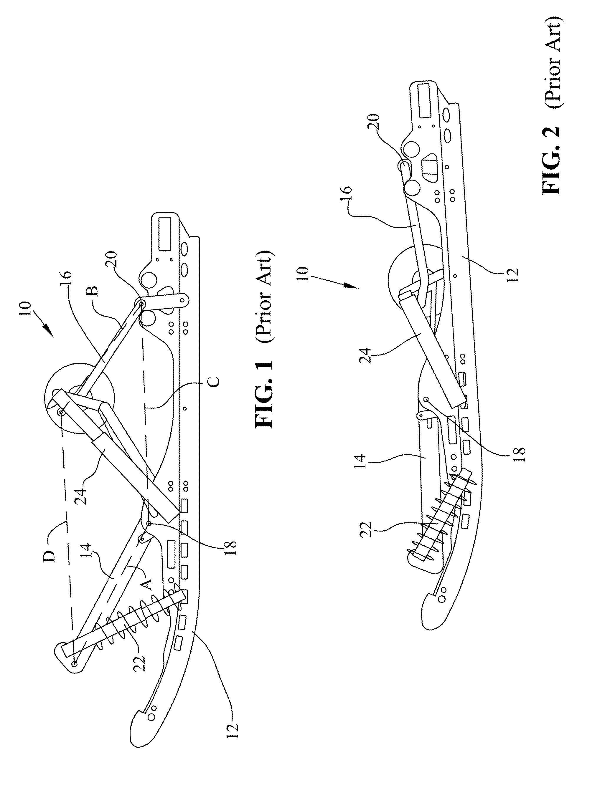
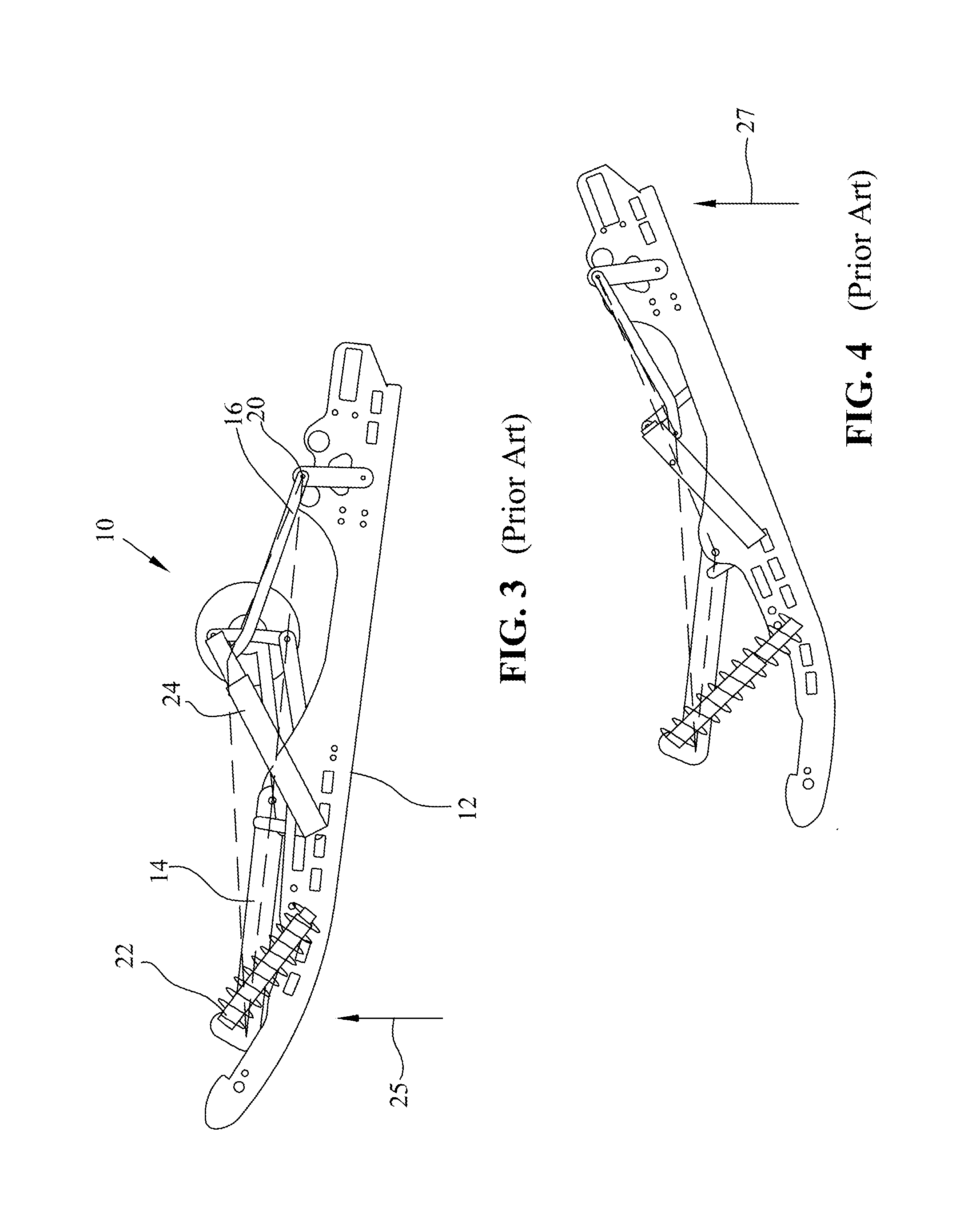
[0092]A progressive rear suspension is disclosed for a rear suspension system of a snowmobile. A progressive suspension is one having a stiffness that increases throughout (or at least substantially throughout) the entire range of suspension travel.

[0093]A diagrammatical depiction of the progressive suspension is shown in FIGS. 8-14, and will be described representatively. This progressive suspension provides improved ride with less bottoming an...


PUM


Abstract

A snowmobile rear suspension is shown comprised of a linear force element (LFE) positioned outside the envelope of the snowmobile endless track. The LFE is attached at one end to the frame and at the other end to a bell crank. The bell crank is operatively connected to the slide rails. When the slide rails collapse in normal operation, the bell crank strokes the LFE, and the suspension is progressive throughout the range.

Description

[0001]This application claims priority from provisional patent application Ser. No. 60 / 776,467 filed Feb. 24, 2006, the disclosure of which is fully incorporated herein by reference.BACKGROUND OF THE INVENTION[0002]The present invention relates to suspension systems for snowmobiles, and more particularly, the present invention relates to snowmobile rear suspensions. In an illustrated embodiment, progressive rate rear suspension architecture for snowmobiles is disclosed.[0003]Performance characteristics of snowmobiles, including the comfort of the ride, depend on a variety of systems and components, including the snowmobile suspension. Typically, a snowmobile suspension includes two systems, a front suspension system for a pair of skis and a rear suspension system for the track.[0004]The rear suspension of a snowmobile supports an endless track driven by the snowmobile engine to propel the machine. The track is supported beneath a vehicle chassis by a suspension that is designed to p...

Claims


Application Information

Patent Timeline
Patent Type & Authority Patents(United States)
IPC IPC(8): B62D55/104B62M29/00
CPCB62D55/104B62M29/00B62M27/02B62M2027/026
Inventor GIESE, TIMOTHY, JAMES
Owner POLARIS IND INC
Features
  • R&D
  • Intellectual Property
  • Life Sciences
  • Materials
  • Tech Scout
  • Unparalleled Data Quality
  • Higher Quality Content
  • 60% Fewer Hallucinations
Learn More