
Flexible trouble light

a trouble light and flexible technology, applied in the field of flexible light, can solve the problems of restricting the usefulness of lights, difficulty in hanging or positioning other trouble lights or flashlights, and devices that may or may not be rechargeabl

Inactive Publication Date: 2014-09-02
MCNABB DANIEL S +1
View PDF4 Cites 4 Cited by
  • Summary
  • Abstract
  • Description
  • Claims
  • Application Information

AI Technical Summary

Benefits of technology

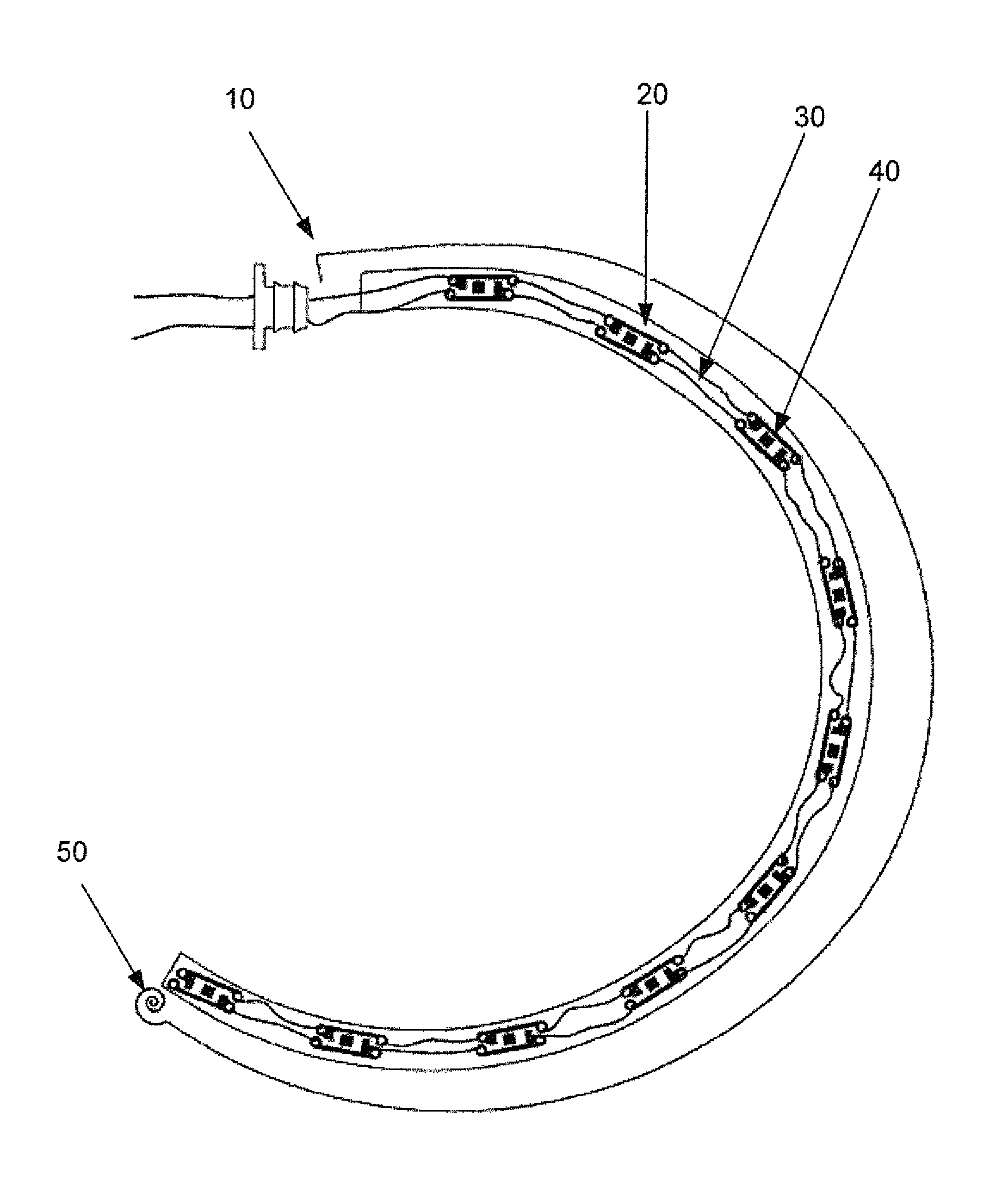
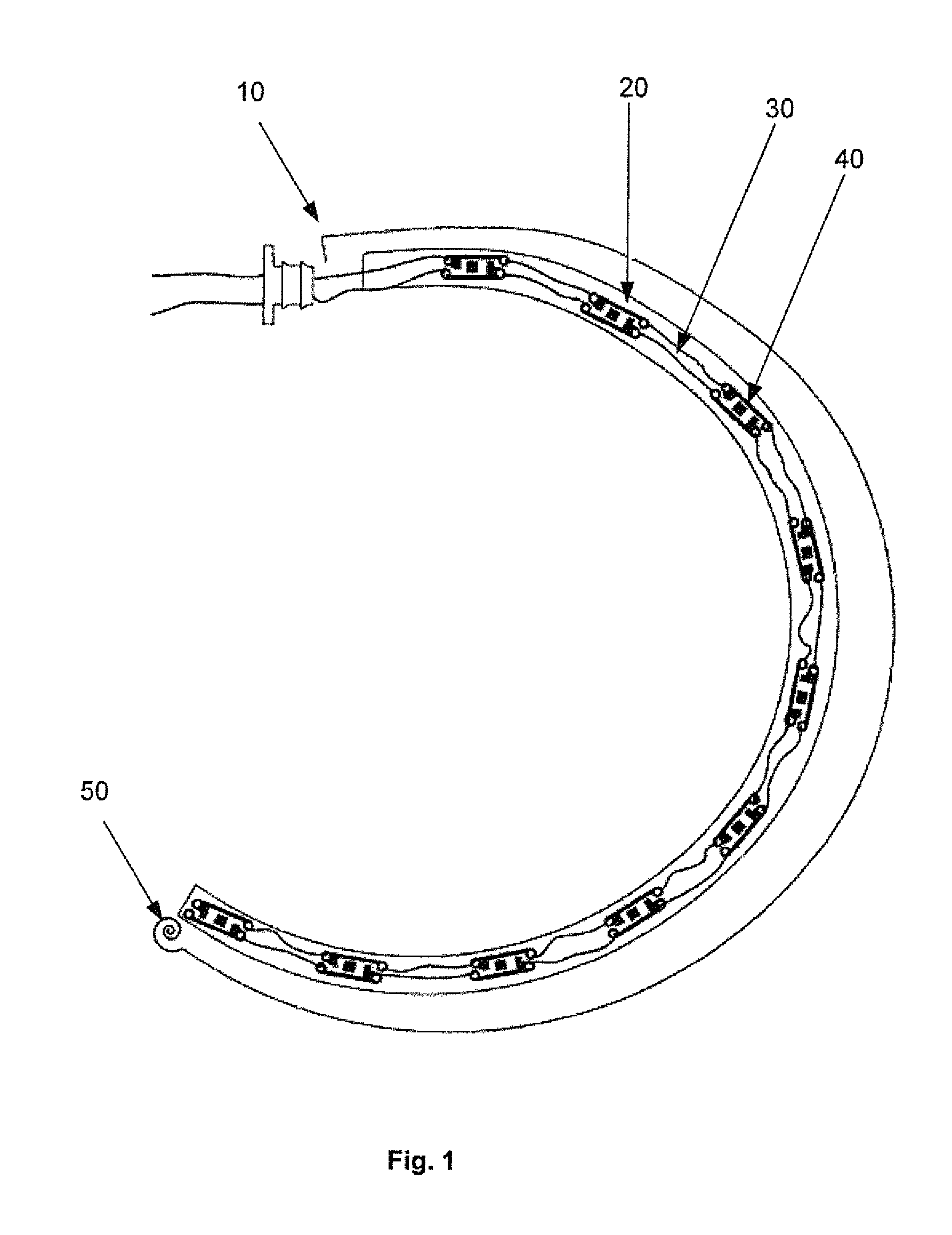
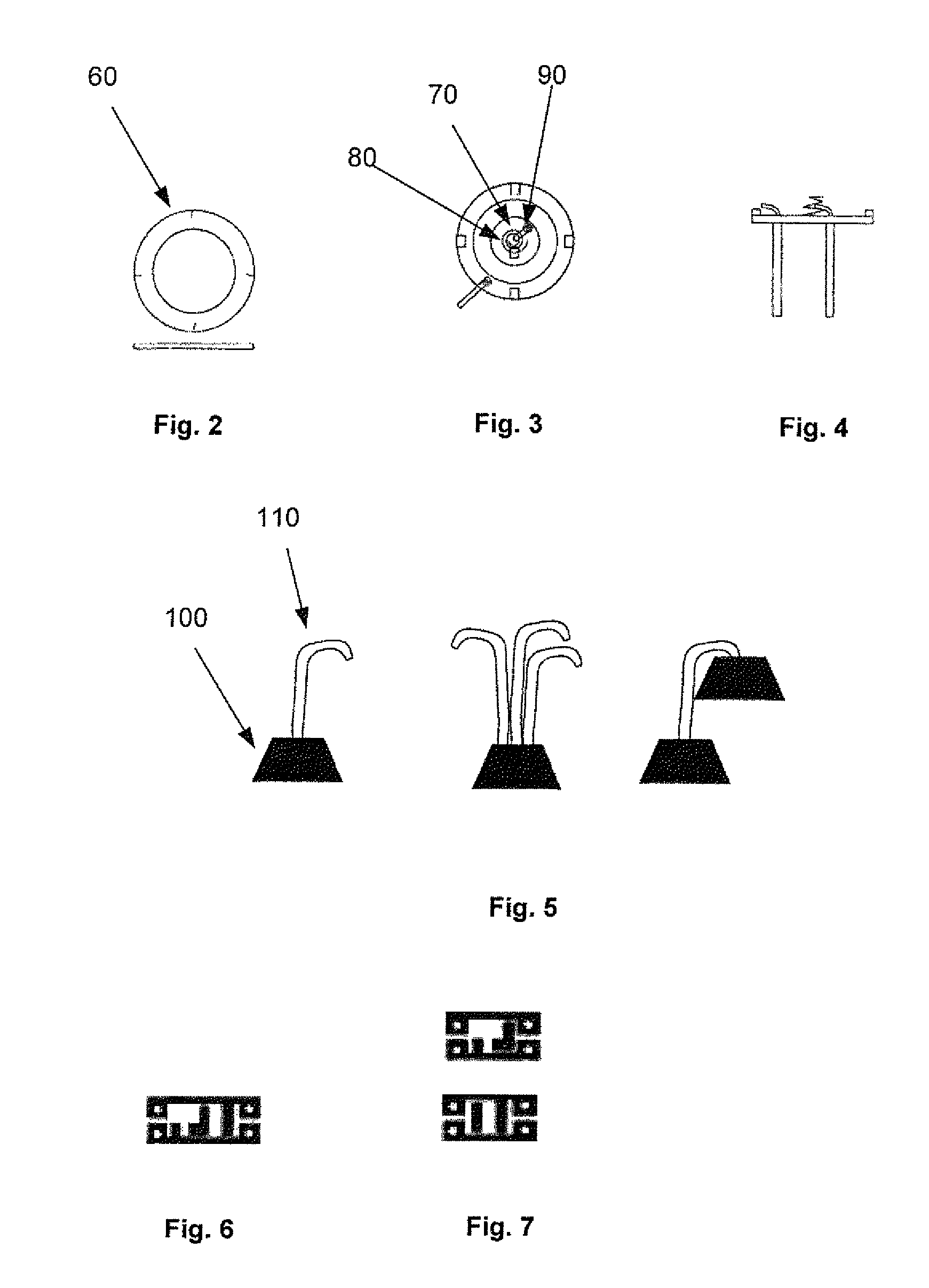
[0003]A highly shapeable lighting device includes sturdy casings for light emitting diodes, flexible wires between the eases of diodes, a shapeable spine, a rechargeable battery pack, and a compact handle holding the batteries and charging port. The shapeable spine allows the device to be straightened for use in a deep dark area, and it can be tightly balled up or folded for easy storage. The flexible outer tube makes it easy to wrap an end around a nearby object, grasping it tightly, casting light all around it. The lights are bright enough to provide good lighting for projects where space to hang or position other trouble lights or flashlights is difficult. The material holding the LEDs also holds the two wires that come out of each end of the LED plug. The device may or may not be rechargeable.
[0014]What is needed is a trouble light that can more easily and dynamically be positioned to provide appropriate lighting for everyday tasks. No other product or patent combines flexibility, recharge ability, a series of plugs with LEDs, and holding power like this device.

Problems solved by technology

The lights are bright enough to provide good lighting for projects where space to hang or position other trouble lights or flashlights is difficult.
The device may or may not be rechargeable.
These lights are restrictive in their usefulness.
The flexible mat can be shaped, but is too large to fit into crevasses.
The light tube fits into crevasses, but its lack of flexibility makes it difficult to position for hands-free use.
Unfortunately, the limpness and lack of formability of a normal rope light made it less than friendly to use.
Also, rope lights produce very little light outside of the tube they are extruded inside of.
This method works great for gently wrapping around banisters, but will not stand up to the stress created by repeatedly bending and shaping around objects.
No other product or patent combines flexibility, recharge ability, a series of plugs with LEDs, and holding power like this device.

Method used


Image

  • Flexible trouble light
  • Flexible trouble light
  • Flexible trouble light

Examples


Embodiment Construction

[0035]This device is so flexible it can be looped several times around a single pipe or tube. It can be wrapped around its own handle, creating a very small profile, easy to store in a toolbox. The small size of the tube allows it to easily be placed inside of areas no other flashlight will fit. This device provides better portable illumination in tight areas than any other current device. The smooth outside of the tube allows it to easily be inserted and withdrawn from tight areas like engine compartments or inside of furnaces.

[0036]The round aluminum wire used to provide flexibility and holding power is able to move 360 degrees, any direction from the handle.

[0037]There is optionally an additional LED at the tip to provide extremely easy to direct directional lighting.

[0038]There is slack in the sets of wires between the LED plugs so using the device will not pull on the wire.

[0039]The LEDs used are Cree, surface mount, 120 degree viewing angle. This allows the light to be cast wi...


PUM


Abstract

A lighting device comprising a sealed transparent flexible outer tube having a handle at a first end. The handle includes a power source. Inside the tube is a flexible wire extending from and attached to the handle. The wire extending the length of the outer tube. Also inside the tube are multiple small lengths of inflexible interior tubing running at least a partial length of the flexible outer tube. Each interior tubing having at least one light emitting diode and at least one resistor inside. The resistors and diodes are connected electronically to a circuit board and the power source.

Description

CROSS-REFERENCES TO RELATED APPLICATIONS[0001]This patent application claims the benefit of provisional patent application Ser. No. 61 / 550,786, filed Oct. 24, 2011, the complete subject matter of which is hereby incorporated herein by reference in its entirety.FIELD OF THE INVENTION[0002]The present invention relates to a flexible light using light emitting diodes (LEDs).BACKGROUND AND SUMMARY[0003]A highly shapeable lighting device includes sturdy casings for light emitting diodes, flexible wires between the eases of diodes, a shapeable spine, a rechargeable battery pack, and a compact handle holding the batteries and charging port. The shapeable spine allows the device to be straightened for use in a deep dark area, and it can be tightly balled up or folded for easy storage. The flexible outer tube makes it easy to wrap an end around a nearby object, grasping it tightly, casting light all around it. The lights are bright enough to provide good lighting for projects where space to ...

Claims


Application Information

Patent Timeline
Patent Type & Authority Patents(United States)
IPC IPC(8): F21V21/00F21S4/00F21S6/00F21S8/00F21S9/02F21V5/04F21V9/00F21V17/00F21V21/03F21V21/06F21V23/04F21Y101/02
CPCF21S6/005F21V17/007F21Y2101/02F21V21/00F21S9/02F21S4/005F21S8/033F21V9/00F21V5/04F21V21/03F21V23/04F21S6/002F21V21/06F21S4/22F21Y2115/10
Inventor MCNABB, DANIEL S.MCNABB, BENJAMIN H
Owner MCNABB DANIEL S
Learn More