

Programmable lighting effect device and system
a control device and programmable technology, applied in the direction of lighting support devices, cathode-ray/electron beam tube circuit elements, lighting and heating apparatus, etc., can solve the problems of high cost, inability to repair or replace, and custom-built controllers,
- Summary
- Abstract
- Description
- Claims
- Application Information
AI Technical Summary
Benefits of technology
Problems solved by technology
Method used
Image

Examples
Embodiment Construction
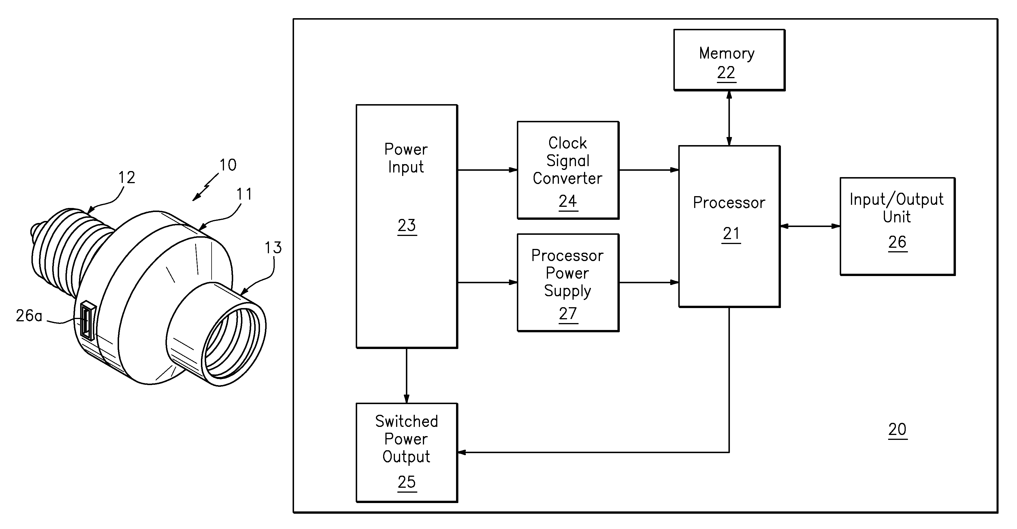
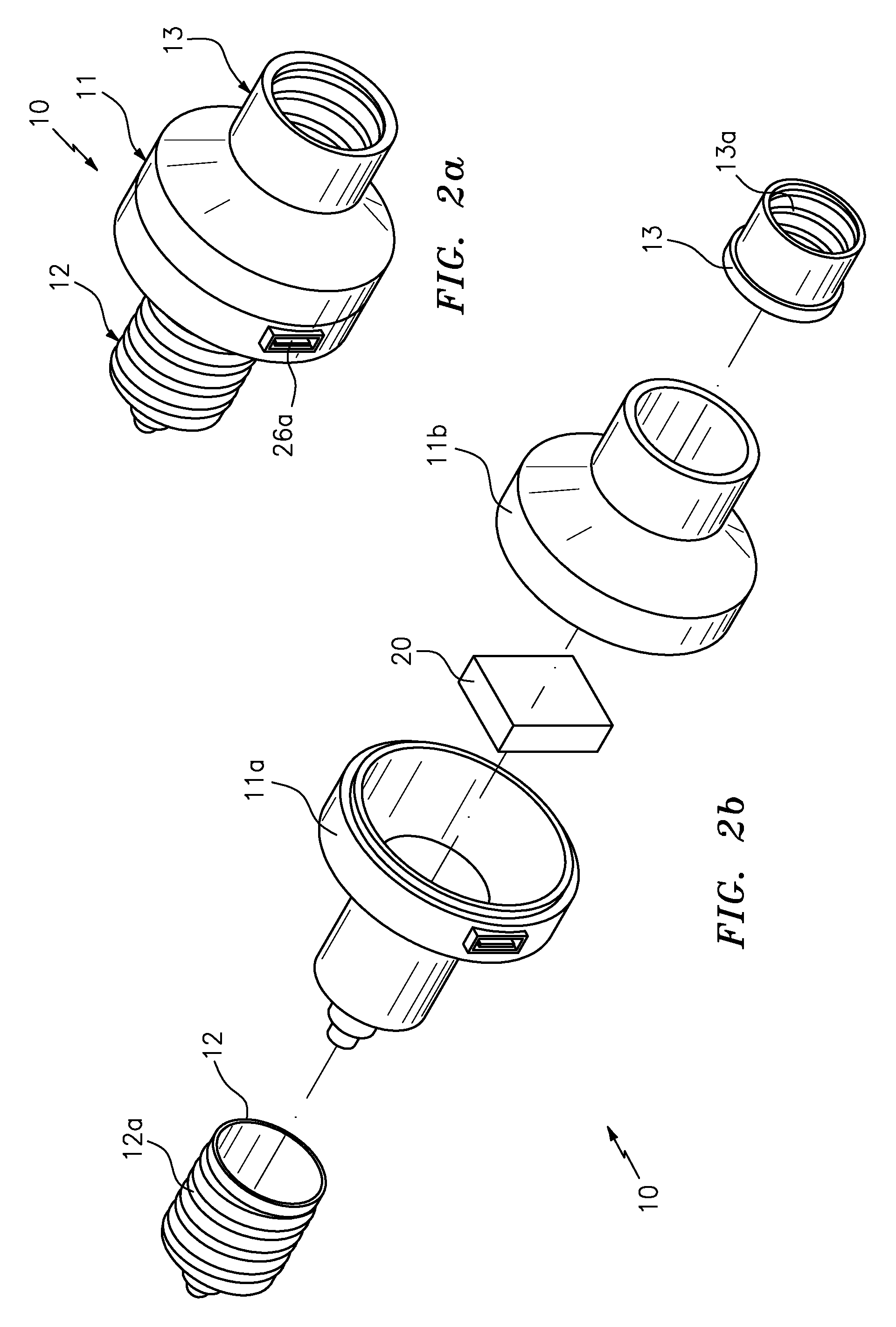
[0020]While the specification concludes with claims defining the features of the invention that are regarded as novel, it is believed that the invention will be better understood from a consideration of the description in conjunction with the drawings. As required, detailed embodiments of the present invention are disclosed herein; however, it is to be understood that the disclosed embodiments are merely exemplary of the invention which can be embodied in various forms. Therefore, specific structural and functional details disclosed herein are not to be interpreted as limiting, but merely as a basis for the claims and as a representative basis for teaching one skilled in the art to variously employ the inventive arrangements in virtually any appropriately detailed structure. Additionally, commonly known articles such as connecting wires, mounting clips and the like may be omitted from the drawings for the sake of clarity. Further, the terms and phrases used herein are not intended t...
PUM
 Abstract
Description
Claims
Application Information