
EL display panel, its driving method, and EL display apparatus

a technology of el display panel and driving method, which is applied in the direction of instruments, semiconductor devices, computing, etc., can solve the problems of display irregularities, difficulty in realizing large-scale and high-definition display panel, and difficulty in controlling and a relatively high price, so as to achieve satisfactory image display and sufficiently charge/discharge the parasitic capacitance

Active Publication Date: 2014-09-02
JOLED INC
View PDF52 Cites 5 Cited by
  • Summary
  • Abstract
  • Description
  • Claims
  • Application Information

AI Technical Summary

Benefits of technology

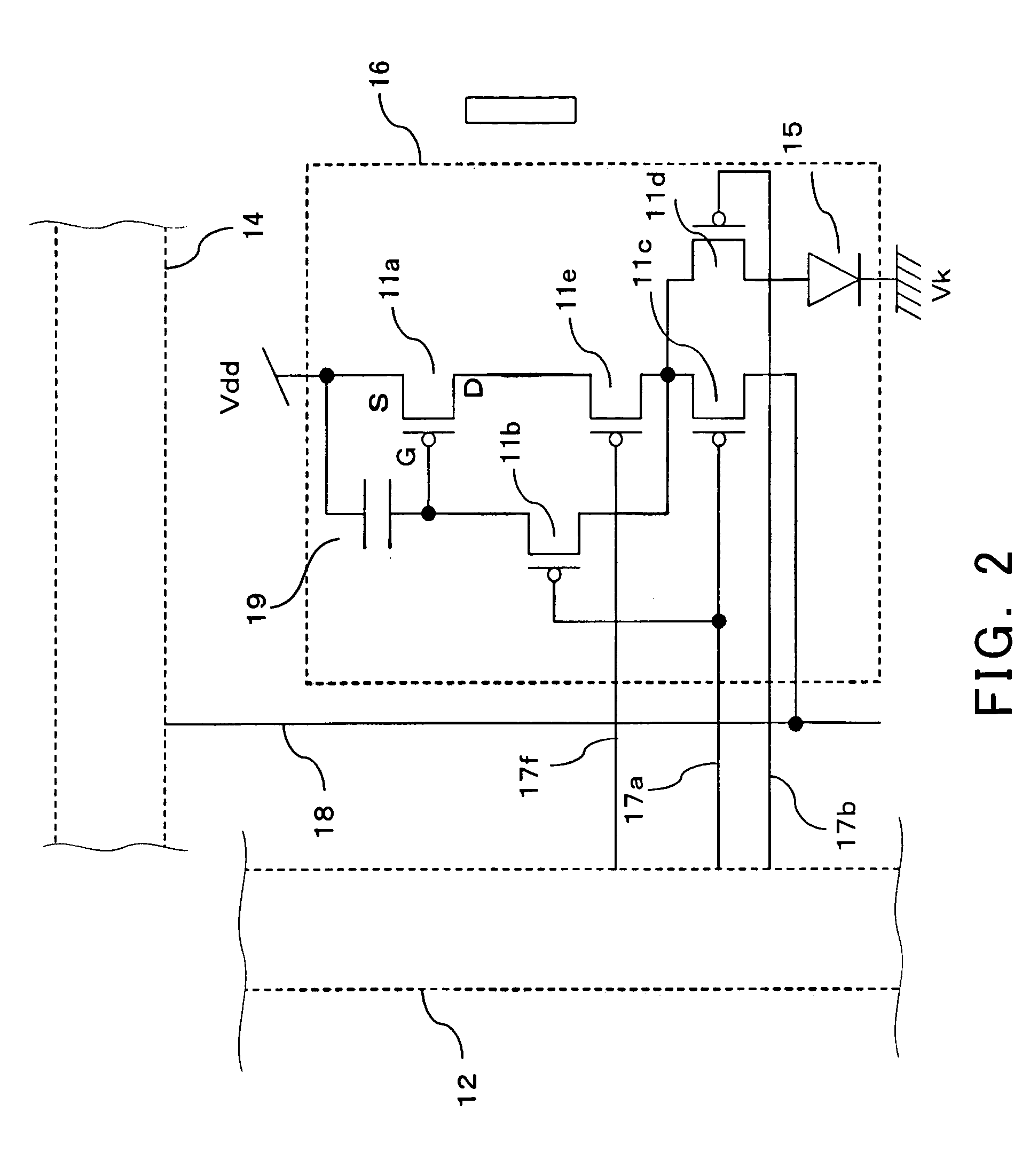
[0014]The present invention has been made in view of the foregoing circumstances. It is an object of the present invention to provide an EL display apparatus which is capable of realizing satisfactory image display by sufficiently charging / discharging the parasitic capacitance present in the source signal line.

Problems solved by technology

Though the former configuration is simple in structure, it has a difficulty in realizing a large-scale and high-definition display panel.
However, it has problems of a technical difficulty in control and of a relatively high price.
Since organic EL devices emit light based on current, the organic EL display panel involves a problem that display irregularities occur if there are variations in transistor characteristics.
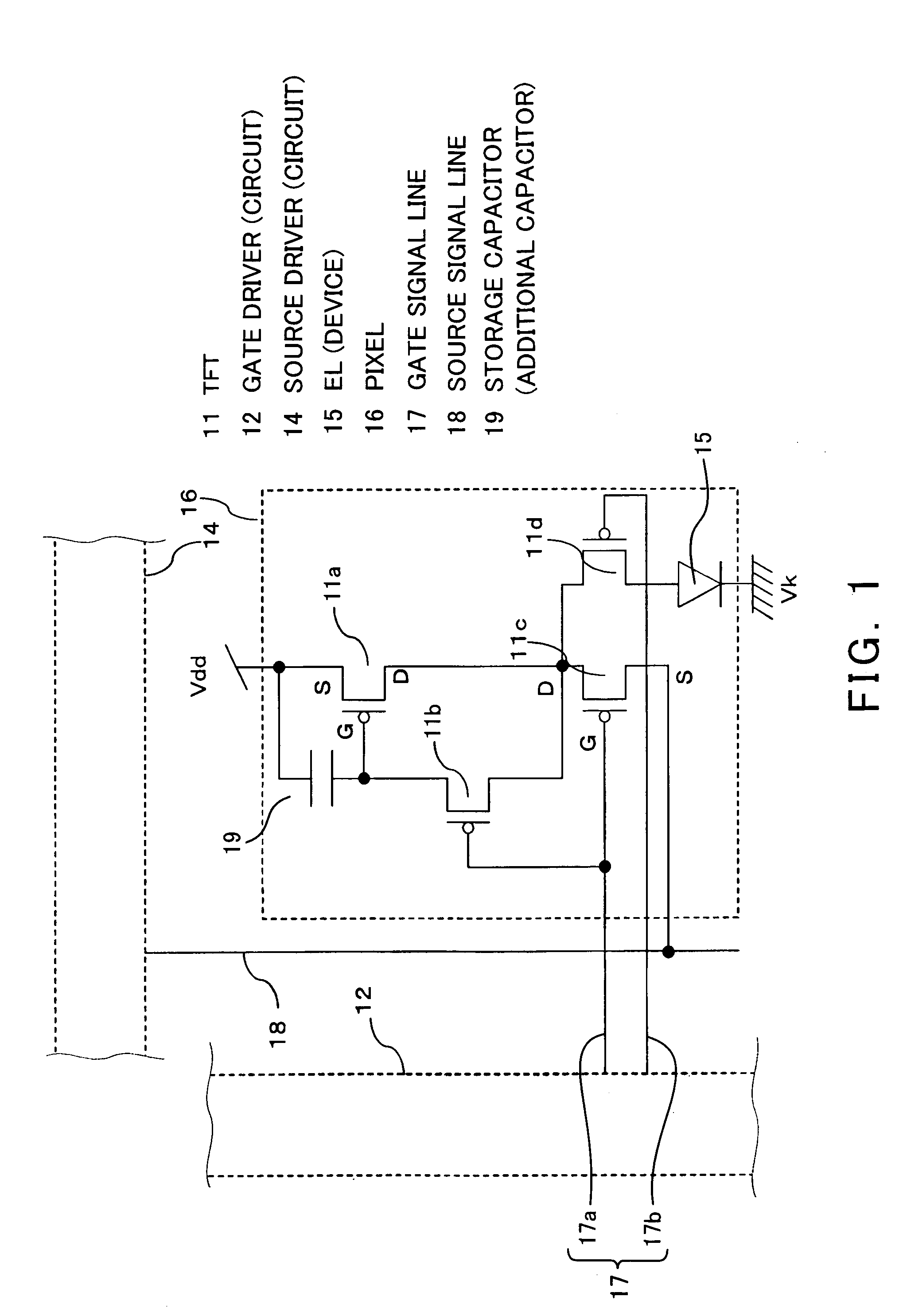
Further, a conventional EL display panel cannot sufficiently charge / discharge the parasitic capacitance which is present in the source signal line 18.
For this reason there arises a problem that in some cases a desired current cannot be fed to pixel 16.

Method used


Image

  • EL display panel, its driving method, and EL display apparatus
  • EL display panel, its driving method, and EL display apparatus
  • EL display panel, its driving method, and EL display apparatus

Examples


Embodiment Construction

[0104]Hereinafter, embodiments of the present invention will be described with reference to the drawings.

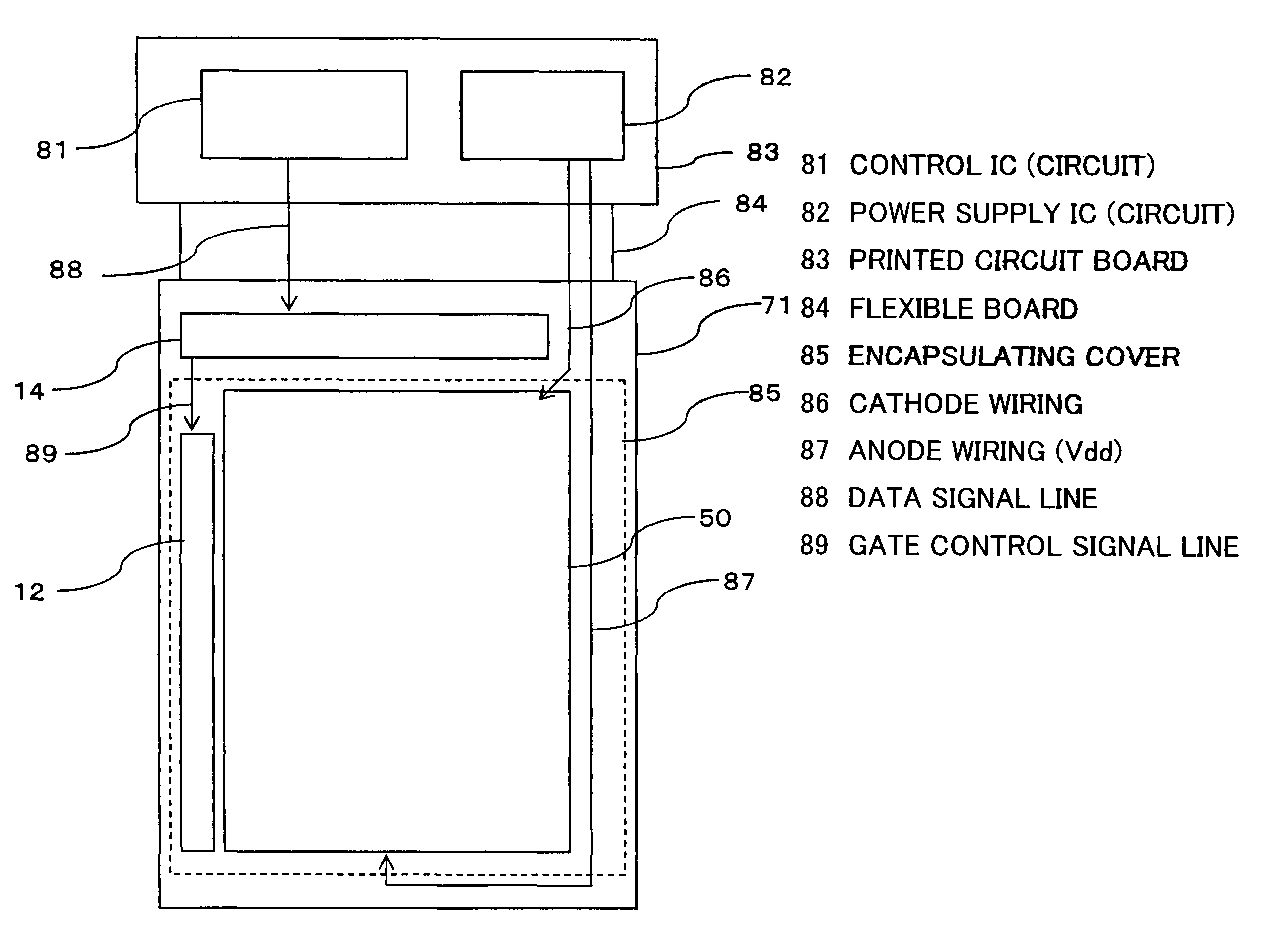
[0105]For easy understanding and / or illustration, each of the drawings in this description may have portions omitted and / or enlarged / reduced. For example, an encapsulating film 111 and the like are shown to be quite thick in the sectional view of a display panel at FIG. 11. On the other hand, an encapsulating cover 85 is shown to be thin in FIG. 10. There are omitted portions. For example, a display panel or the like according to the present invention needs to have a phase film such as a circularly polarizing plate for antireflection. However, such a phase film is omitted from the drawings used in this description. This holds true for other drawings. Like numerals, characters or the like designate parts having identical or similar forms, materials, functions or operations.

[0106]It is to be noted that the details to be described with reference to the drawings may be combined with ...


PUM


Abstract

An EL display apparatus according to the present invention includes EL device (15) adapted to emit light at a luminance corresponding to a current fed thereto. A source driver (14) outputs a current higher than a current corresponding to an image signal to the EL device (16) through a source signal line (18). This operation charges / discharges a parasitic capacitance present in the source signal line (18). A transistor (11d) formed between the EL device (15) and the source driver (14) operates so that the EL device (15) is fed with the current for only a part of a one-frame period. As a result, the El device (15) emits light for only the part of the period.

Description

TECHNICAL FIELD[0001]The present invention relates to an EL display apparatus employing an organic or inorganic electroluminescence (EL) device and, more particularly, to an EL display apparatus capable of feeding an EL device with a desired current, a method of driving the same, and an electronic apparatus provided with such an EL display apparatus.BACKGROUND ART[0002]In general, an active-matrix display apparatus has a multiplicity of pixels arranged in matrix and displays an image by controlling the intensity of light pixel by pixel in accordance with image signals given. When, for example, liquid crystal is used as an electro-optic substance, the transmittance of each pixel varies in accordance with the voltage applied to the pixel. The basic operation of an active-matrix image display apparatus employing an organic electroluminescence (EL) material as an electro-optic converting substance is the same as in the case where liquid crystal is used.[0003]A liquid crystal display pan...

Claims


Application Information

Patent Timeline
Patent Type & Authority Patents(United States)
IPC IPC(8): G09G3/30G09G3/32G09G5/02H01L27/32
CPCG09G3/3241G09G3/325G09G2310/0256G09G2300/0842G09G2300/0809G09G2300/0814G09G2310/0218G09G2320/0257G09G2320/0261G09G2310/027G09G2310/0248G09G2300/0861G09G2310/0205G09G2320/043G09G2310/0251G09G5/02G09G2320/0606H01L27/3244G09G2320/0626G09G2320/0247G09G2320/06G09G3/3266G09G2300/0819G09G2300/0852G09G2310/0289H01L27/124G09G2320/0653H01L27/1255G09G3/32H10K59/12H10K59/126G09G3/30H10K50/846H10K50/8428H10K59/35H10K59/1213H10K59/1216H10K50/86H10K50/844H10K59/352G09G3/3233G09G3/3258G09G2300/0404G09G2310/08G09G3/2003G09G3/2007G09G3/3275G09G2300/0413H01L27/1251H01L29/78645G09G2320/0646H01L27/127H01L27/156H01L29/78672H01L33/56H01L33/58H05K999/99
Inventor TAKAHARA, HIROSHITSUGE, HITOSHI
Owner JOLED INC
Learn More