Polymer-based bracket system for metal panels

a technology of metal panels and polymers, applied in the direction of parkings, walls, ceilings, etc., can solve the problems of varying the contraction and expansion rate of different materials, shortening the warrantee and life cycle, and significant wear on any given system

Active Publication Date: 2014-09-09
ADVANCED ARCHITECTURAL PROD
View PDF53 Cites 28 Cited by
  • Summary
  • Abstract
  • Description
  • Claims
  • Application Information

AI Technical Summary

Benefits of technology

[0002]One aspect of the present invention is a system for supporting exterior cladding units on a substrate of a structure. The system includes a polymeric bracket system made up of a plurality of polymeric bracket members, and each of the bracket members have at least one anchor section, at least one web section and at least one support section. The anchor section(s) attaches the bracket member to the substrate, the web section(s) connects the anchor section(s) to the support section(s), and the support section(s) attaches to the exterior cladding unit. The polymeric bracket members provide a thermal break from the exterior cladding unit to the substrate of the building structure. In the polymeric bracket system, each of the polymeric bracket members are mounted to the building structure to form rows thereby forming channels between the exterior cladding units and the substrate when the exterior cladding units are mounted. A ventilation system having a plurality of vents is formed by the mounting of the exterior cladding units to the polymeric bracket system.

Problems solved by technology

Products of this type are subject to shorter warrantees and life cycles due to the fact that the product is glued or otherwise bonded and is subject to damage and shortened life spans from thermal cycling which causes varying rates of contraction and expansion of the different materials and therefore wears significantly on any given system.
Furthermore, these systems often require like materials to be in contact with each other which can lead to reactions such as oxidation which can corrode these materials over time.

Method used


Image

  • Polymer-based bracket system for metal panels
  • Polymer-based bracket system for metal panels
  • Polymer-based bracket system for metal panels

Examples


Embodiment Construction

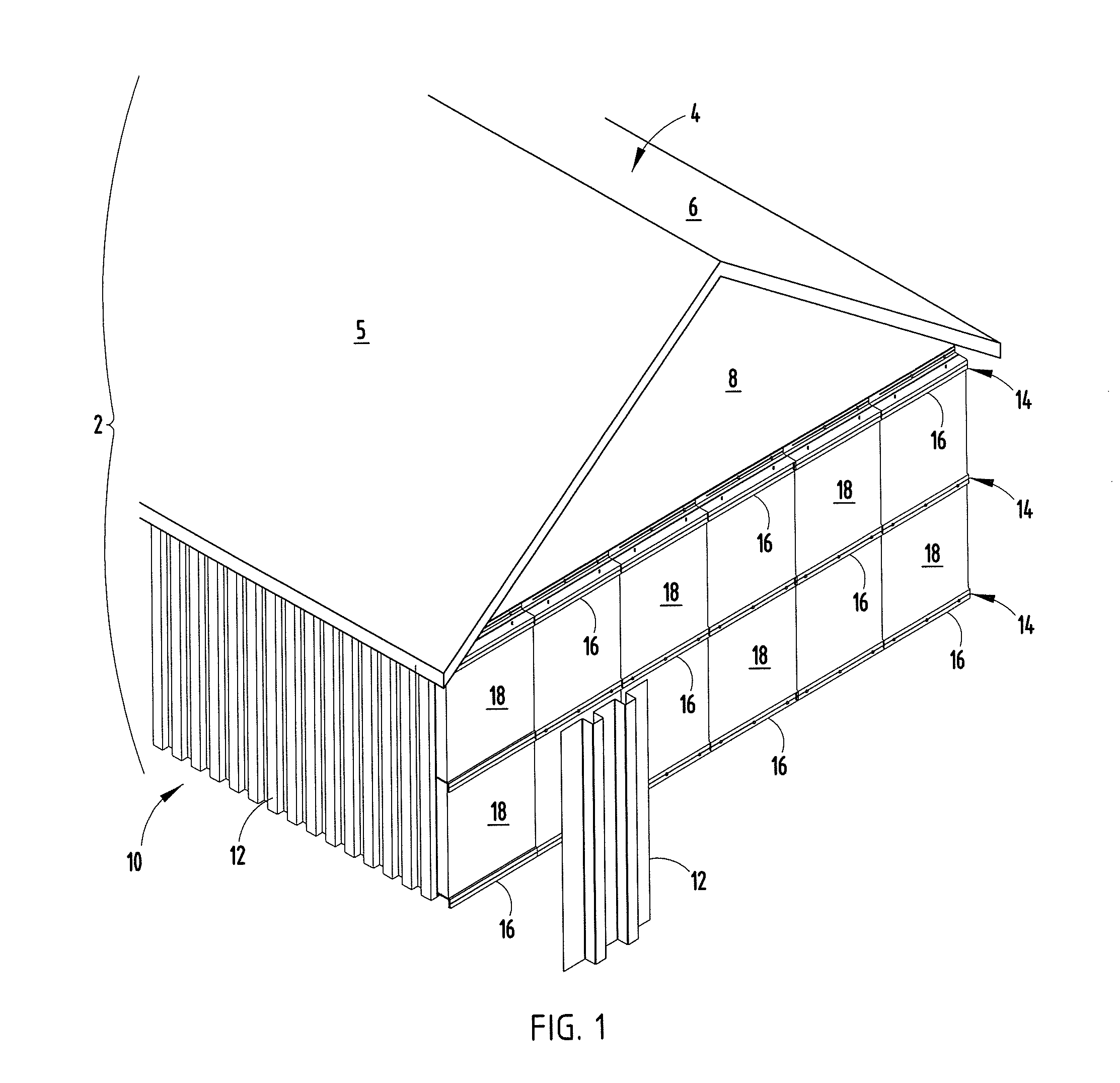
[0027]For the purposes of description herein, the terms “upper,”“lower,”“right,”“left,”“rear,”“front,”“vertical,”“horizontal,” and derivatives thereof shall relate to the invention as oriented in FIG. 1. However, it is to be understood that the invention may assume various alternative orientations, except where expressly specified to the contrary. It is also to be understood that the specific devices and processes illustrated in the attached drawings, and described in following specification, are simply exemplary embodiments. Hence, specific dimensions and other physical characteristics relating to the embodiments disclosed herein are not to be construed as limiting, unless expressly stated otherwise.

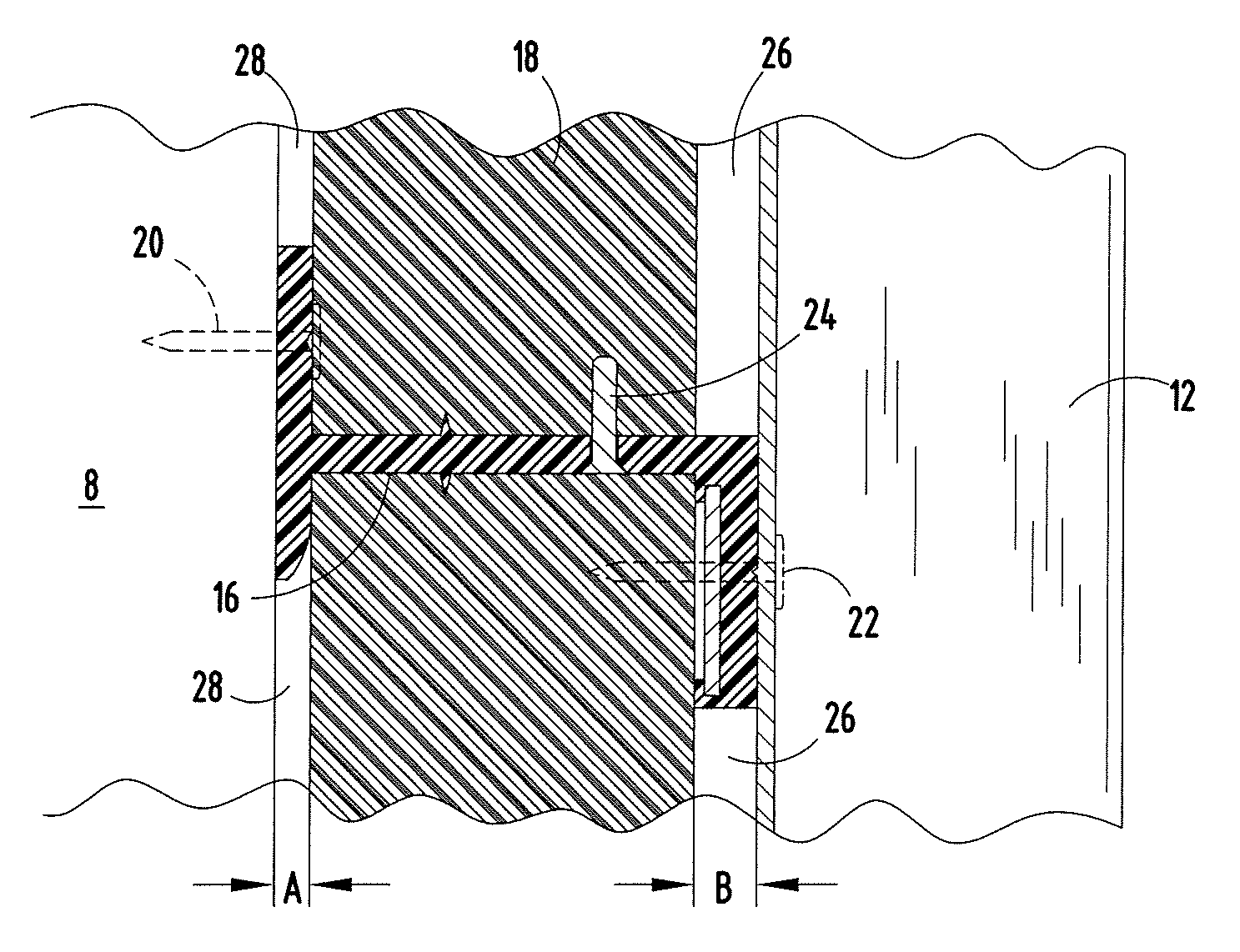
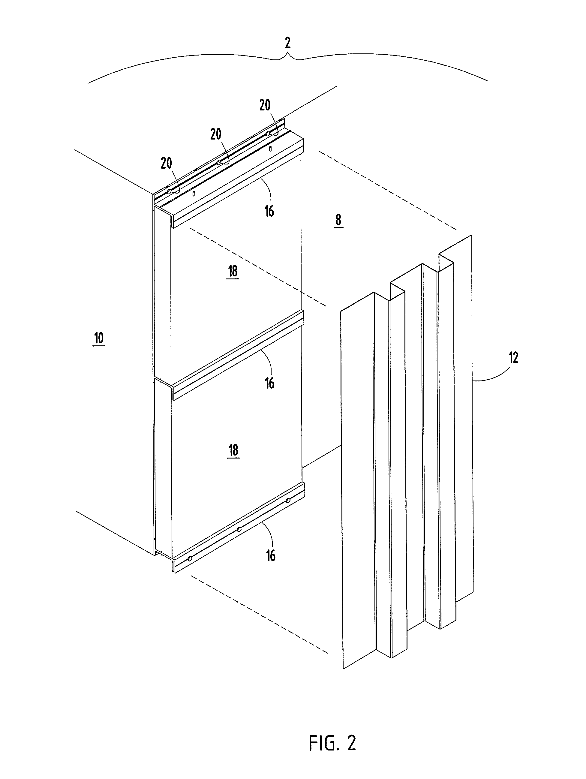
[0028]The reference numeral 2 (FIG. 1) generally designates one embodiment of the present invention wherein a building structure includes a roof 4 with sides 5, 6, a front wall 8, and a side wall 10. The side wall or building substrate 10 is covered by exterior cladding units 12 which, ...


PUM


Abstract

A system for supporting exterior panels on a substrate of a building structure. The system has a plurality of polymeric bracket members, and each of the bracket members have at least one anchor section, at least one web section and at least one support section. The polymeric bracket members provide a thermal break from the exterior panel to the substrate of the building structure. A plurality of exterior cladding units are held in place by the bracket members. A plurality of vents are disposed between the panels and the exterior panels, and a plurality of vents are also disposed between the panels and the substrate, thereby forming a ventilation system.

Description

BACKGROUND OF THE INVENTION[0001]In the past, in order to provide a highly thermally efficient (metal) wall or (metal) roof assembly for a building enclosure, it has been necessary for metal materials, typically an exterior and interior metal skin, to be bonded to either side of an insulated panel core inside a factory thereby creating a foam panel. These metal skins are typically profiled and have offsets in them to prevent the exterior metal skin from contacting the interior metal skin. This is done in an effort to prevent metal to metal contact thereby reducing thermal conductivity from the outside of the building. Heat travels in the path of least resistance such that heat can invade a system and affect an interior atmosphere through relatively finite pathways such as fasteners and the like that have metal to metal contact with exterior conditions. Most applications of metal roof and wall assemblies retain at least some form of metal to metal contact through metal anchors, faste...

Claims


Application Information

Patent Timeline
Patent Type & Authority Patents(United States)
IPC IPC(8): E04B2/88E04F13/08E04F13/12
CPCE04F13/12E04F13/0817E04F13/0875E04B1/40E04B1/7645E04B1/7654E04B2001/405E04B2001/7679E04F13/007E04F13/22E04B1/388E04B2001/389E04F13/0803
Inventor KRAUSE, G., MATT
Owner ADVANCED ARCHITECTURAL PROD
Why Eureka
Try Eureka