Thermally broken sunshade anchors

a sunshade and anchor technology, applied in the field of thermally broken sunshade anchors, can solve the problems of increasing the u-value of the curtain wall, degrading the heat transfer resistance of the otherwise thermally broken curtain wall, and reducing the negative thermal impact of the curtain wall

Active Publication Date: 2009-10-13
YKK AP AMERICA INC
View PDF19 Cites 28 Cited by
  • Summary
  • Abstract
  • Description
  • Claims
  • Application Information

AI Technical Summary

Benefits of technology

[0029]Another advantage of the present invention can be to provide thermally broken sunshades.
[0030]A further advantage of the present invention can be to reduce negative thermal impact on curtain walls and / or buildings by sunshades.
[0031]Yet another advantage of the present invention can be to provide improved devices having pour and debridge thermal breaks.
[0032]Other advantages may include providing new methods related to sunshade anchors, sunshades and thermal breaks.
[0033]Additional features and advantages of the present invention are described in, and will be apparent from, the following

Problems solved by technology

The energy efficiency and performance of buildings is a concern, due to, for example, rising energy costs and environmental concerns associated with non-renewable energy sources.
However, sunshades, sunshade attachment structures and sunshade attachment methods have not been thermally broken.
The additional heat load placed on the curtain wall by the sunshade is in direct conflict to the energy performance of the overall curtain wall system and may even degrade the heat transfer resistance of the otherwise thermally broken curtain wall.
A non-thermally broken sunshade attached directly to the mullion of the curtain wall increases the U-value of the curtain wall and reduces the energy performance of the wall as well.
The non-thermally broken sunshade may also have a negative effect on the energy efficiency of the building.
However, the shading benefits of the sunshade may be at least partially offset by the diminished energy performance of the building curtain wall caused by the attachment of the sunshade which is a large metallic appendage.
Existing sunshades can negatively impact the curtain wall's U-value to some extent.
Pour and debridge thermal breaks have also had problems with dry shrinkage and potentially inadequate shear strength between the thermal break and aluminum components.

Method used


Image

  • Thermally broken sunshade anchors
  • Thermally broken sunshade anchors
  • Thermally broken sunshade anchors

Examples


Embodiment Construction

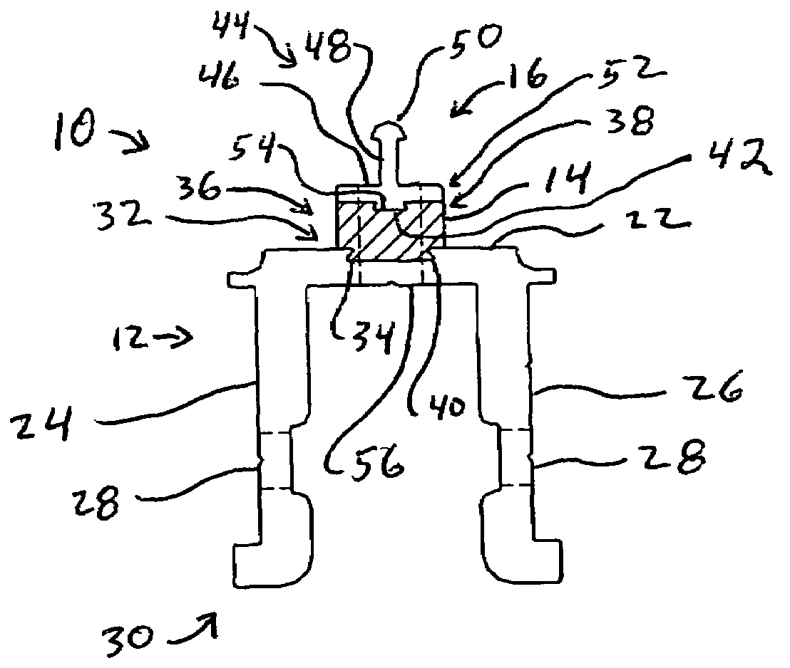
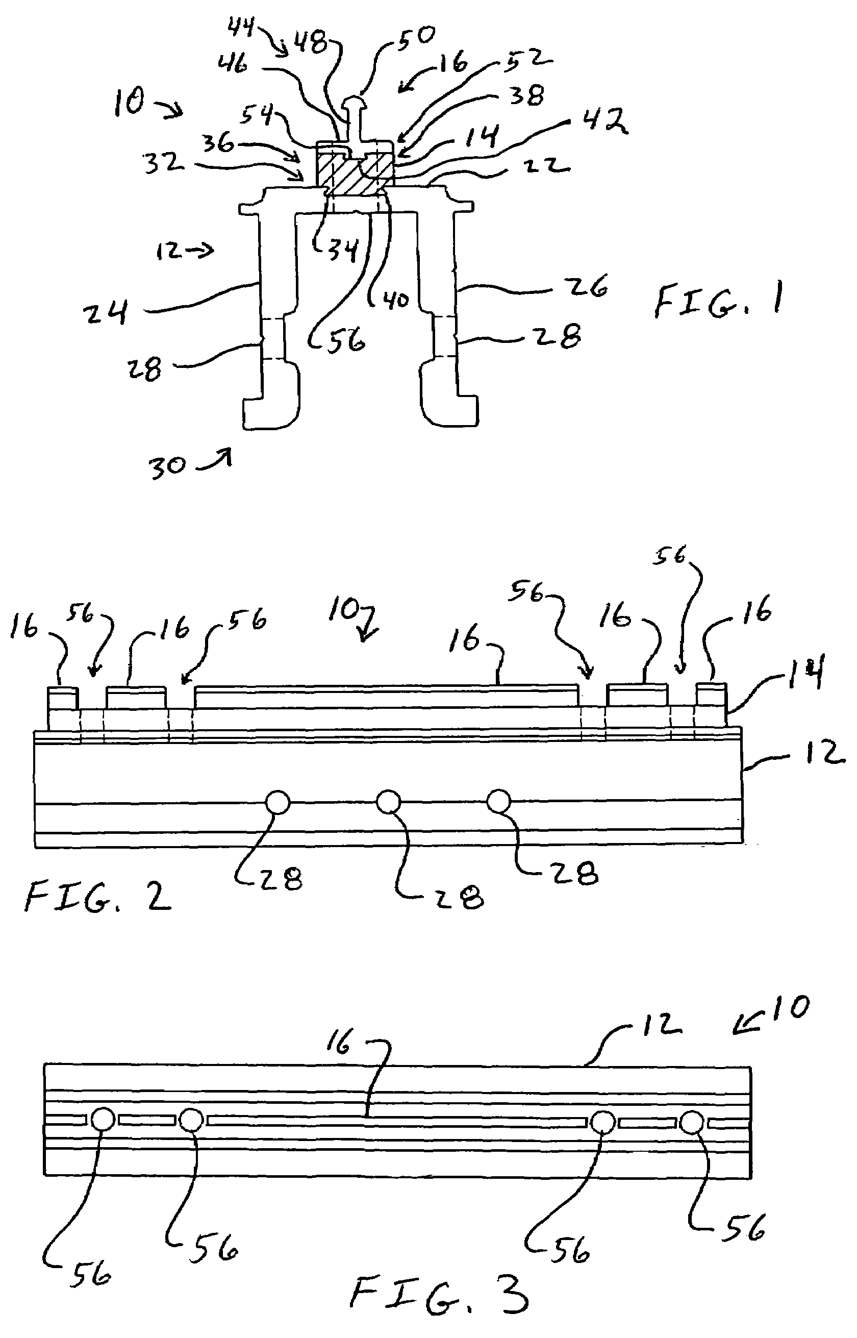
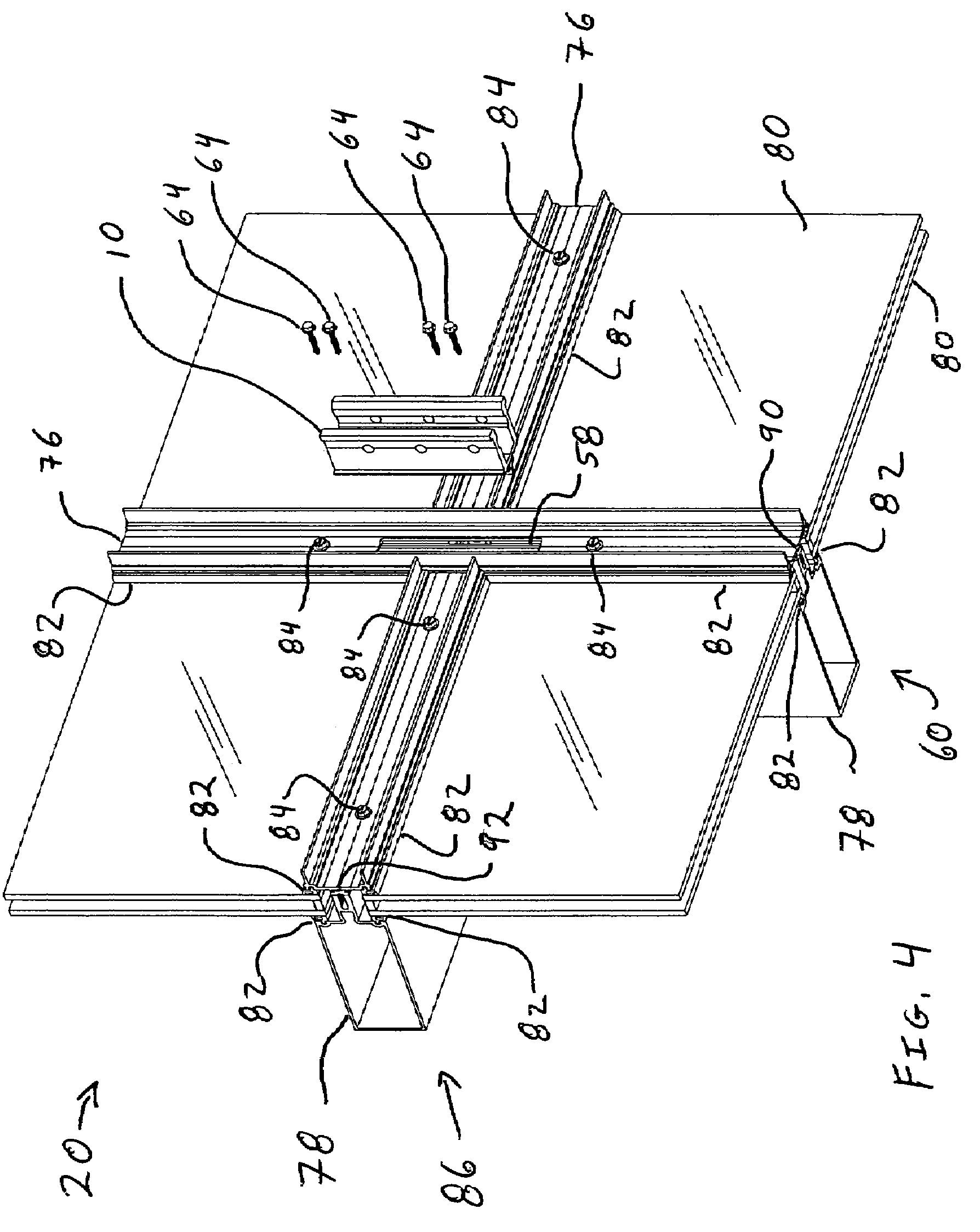
[0043]One example of a thermally broken sunshade anchor 10 according to the present invention is shown in FIGS. 1-3. The thermally broken sunshade anchor 10 has a body 12, a thermal break 14 and a wall attachment member 16. The thermally broken sunshade anchor 10 attaches a sunshade 18 to a curtain wall 20 as shown in FIGS. 4-7. The thermally broken sunshade anchor 10 securely fastens the sunshade 18 in a cantilevered manner to the curtain wall 20 with sufficient strength to overcome at least combined wind loads, dead loads and snow loads applied to the sunshade 18.

[0044]Referring to FIGS. 1-3, the body 12 of the thermally broken sunshade anchor 10 has a base 22 and arms 24, 26, each arm extending from opposite edge portions of the base 22. The example of the body 12 is shown as having a channel shape; however, the body 12 can have any shape or structure as desired. Mounting holes 28 are provided in each of the arms 24, 26. The channel body 12 has a sunshade attachment portion 30 fo...


PUM


Abstract

A thermally broken sunshade anchor can attach a sunshade to a mullion of a curtain wall of a building structure. The thermally broken sunshade anchor has a body for connection to the sunshade, a wall attachment member for attachment to the curtain wall, and a thermal break between the body and the wall attachment member. The thermal break is positioned adjacent a thermal break location portion of the body and adjacent a thermal break location portion of the wall attachment member. The thermal break resists heat transfer such that the body and the wall attachment member are substantially thermally isolated from each other by the thermal break. The thermal break can be formed by pour and debridge processes.

Description

BACKGROUND OF THE INVENTION[0001]Embodiments of the present invention pertain to thermally broken sunshade anchors. The present invention also pertains to sunshade assemblies. Embodiments of the present invention pertain to pour and debridge thermal breaks, particularly for sunshade anchors. The present invention also pertains to methods related to sunshade anchors, sunshade assemblies, and pour and debridge thermal breaks.[0002]Sunshades are often used on the outside of commercial architectural projects or buildings to shade large expanses of glass from sunlight. The sunshades are attached to the exteriors of the buildings and extend outward away from the buildings. The sunshades have louvers which reduce the amount of sunlight that reaches the buildings. The sunshades can mitigate possible solar heat gain to the inside of the buildings from solar light passing through the glass. The energy efficiency and performance of buildings is a concern, due to, for example, rising energy cos...

Claims


Application Information

Patent Timeline
Patent Type & Authority Patents(United States)
IPC IPC(8): E04D13/18E04H14/00
CPCE04B2/96E04F10/08Y02B10/20
Inventor BRAUNSTEIN, RICHARD
Owner YKK AP AMERICA INC
Why Eureka
Try Eureka