Line leak detector

a leak detection and leak detection technology, applied in the direction of instruments, fluid-tightness measurement, liquid/fluent solid measurement, etc., can solve the problems of costly and time-consuming clean up or remediation, leakage into the environment of petroleum products, including gasoline, and achieve the effect of avoiding flow rate restrictions on fuel delivery lines

Inactive Publication Date: 2007-07-19
OPW FUELING COMPONENTS
View PDF54 Cites 16 Cited by
  • Summary
  • Abstract
  • Description
  • Claims
  • Application Information

AI Technical Summary

Benefits of technology

[0016]Also, the invention in various embodiments contemplate use of a biasing member to bias the piston against the anticipated ranges of volumetric changes for the fuel volumes to be tested. For example, the biasing member may be configured as a constant or variable rate spring, a weight, an electromagnet, a permanent magnet, a regulated fluid supply, or a sealed gas pocket. This combination of elements may eliminate artifact sensed volumetric changes resulting from the progressive compression and expansion of air within the liquid volume sensed as well as provide other advantages.
[0017]Accordingly, the invention provides numerous and significant advantages over prior leak detection systems such as those of U.S. Pat. No. 5,091,716. More data points are gathered in significantly less time. Significantly smaller changes in volume are detected over significantly reduced time periods, thus minimizing absolute leak volumes. The impact of thermal variation caused changes is substantially reduced since thermal changes require time and the test window provided by the invention is significantly shorter than in prior systems, resulting in less artifact impact from thermal changes. Existence of air pockets in the fuel volume may be eliminated as a volume change factor resulting from use of a constant force or pressure biasing member. And significantly, fuel line flow rates are not adversely impacted upon installation of the invention since it is simply ported to the line and not inserted or spliced into the line as a choke point as was required in prior devices.
[0018]As a result of these and other features of the invention, a larger number of data points gathered over a shorter period of time, as compared to past systems, can be analyzed by appropriate algorithms (not part of this invention) to provide a more realtime indication of smaller leaks which can be acted on to prevent costly adverse environmental impact, and without restricting delivery system flow. EPA standards or minimums are exceeded on the favorable side and the leak detection capabilities of the invention provide enhanced integrity of fuel delivery systems.

Problems solved by technology

Leakage into the environment of petroleum products, including gasoline, is damaging to surrounding soils and water.
Once a leak is detected, clean up or remediation is costly and time consuming.
Leaks of fuel from the tank or from the interconnecting pipe lines to the dispensers can cause significant environmental damage.
While such a device is accurate to a certain degree, certain features of the device limit the overall performance and the degree of accuracy which can be attained.
Since all the fuel must flow through the sensing device, the device thus constitutes a choke point in the fuel line, restricting the delivery of fuel through the line beyond the capacity of the larger line itself.
Such devices are capable of measuring changes in the linear position of the core over certain ranges of movement, but the data provided is limited in that such devices can only register certain finite changes of position over the design stroke of the piston.
As such, this known device has certain accuracy limitations in terms of the preciseness of its ability to detect minute positional changes in piston displacement smaller than the capacity of the inductive system to measure.
In addition, the collection of the limited data which is sensed in such devices requires certain minimum time periods.
In other words, it takes a significant time period to collect sufficient data for analysis.
The combination of a limited range of positional changes or data points with minimum times necessary for accumulation and data analysis restrict the sensitivity and timeliness of such prior devices, thus limiting the accuracy of the devices and their responsiveness in detecting leaks and providing leaking control.
These limitations, together with others, result in a system which is better than having no detection, but which can still permit undetectable leakage or leakage over small periods of time which can accumulate to adversely impact the environment.
It is also recognized that even though current EPA standards are restrictive, small leaks which are undetectable under current EPA detection performance standards can accumulate over time to constitute massive long term environmental damage.

Method used


Image

  • Line leak detector
  • Line leak detector
  • Line leak detector

Examples


Embodiment Construction

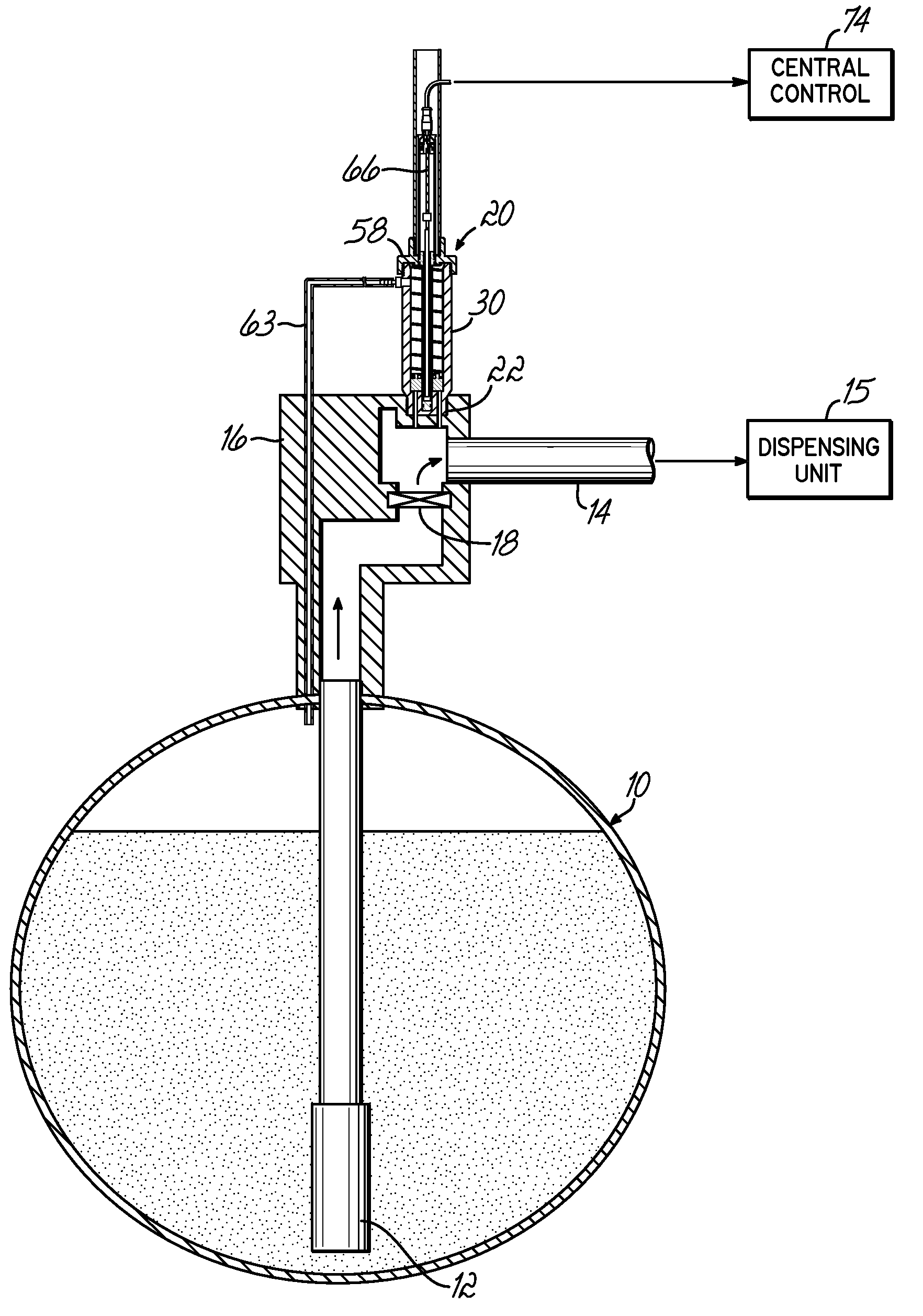
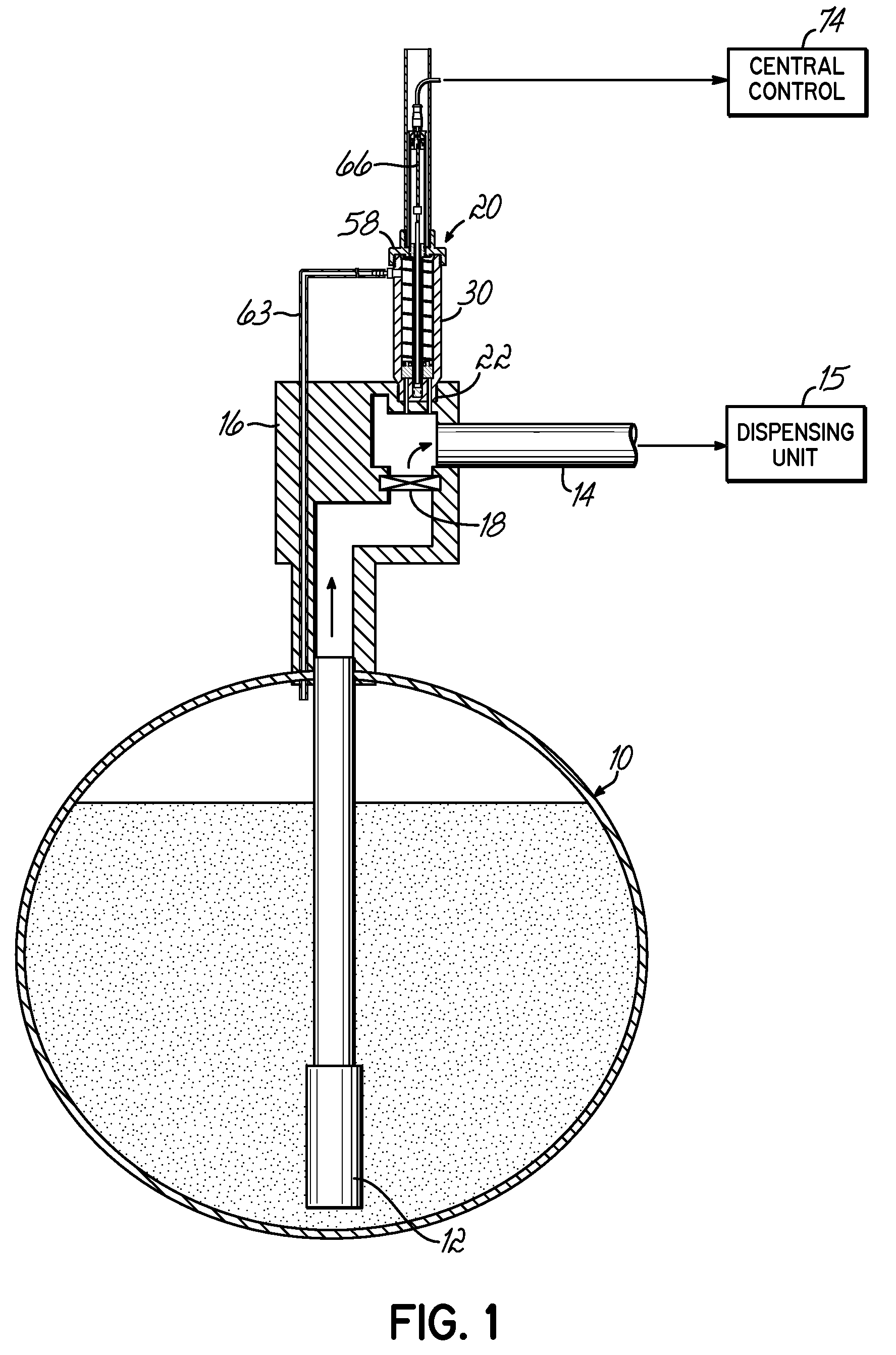
[0031]An exemplary fuel dispensing system of the invention is shown in FIG. 1 and generally includes an underground storage tank (“UST”) 10 for storing a fuel, a submersible pump 12 located in the tank 10, and a fluid conduit line 14 that transports the fuel under pressure to one or more dispensing units 15, shown schematically in FIG. 1. Typically, the fluid conduit line 14 is coupled to the submersible pump 12 via a pump manifold 16 that is typically located external to tank 10, such as in a covered manway. Pump manifold 16 includes a check valve 18 for preventing fuel from flowing back into tank 10. Because check valve 18 prevents any fuel from flowing back into tank 10, when the dispensing unit 15 is off, thus preventing fuel from flowing from conduit line 14, the fluid conduit line 14 defines a closed system containing an amount or volume of fuel that depends on several factors including length of conduit line 14, size of conduit line 14, and other factors. As mentioned above, ...


PUM


Abstract

A leak detector for detecting volumetric changes in a liquid volume includes a biased piston disposed in a housing and a liquid passage extending from the liquid volume to an expansible chamber defined by the housing and piston. The leak detector further includes a magnetostrictive sensor including a magnetostrictive waveguide, a magnet operably coupled to the piston and moveable therewith and pulsing and detection devices for detecting the position of the magnet along the magnetostrictive waveguide. A method of using the detector includes exposing the expansible chamber to liquid from the liquid volume and sensing the changes in the liquid volume magnetostrictively by causing relative movement between the waveguide and the magnet to obtain data representative of piston movement which is responsive to volumetric changes in the liquid volume.

Description

CROSS REFERENCE TO RELATED APPLICATIONS[0001]This application claims priority to provisional patent application Ser. No. 60 / 760,116 filed on Jan. 19, 2006, the disclosure of which is expressly incorporated by reference herein in its entirety.FIELD OF THE INVENTION[0002]This invention relates to leak detection and has particular application to the detection of leakage from pressurized fuel delivery lines in dispensing operations such as gas stations.BACKGROUND OF THE INVENTION[0003]Leakage into the environment of petroleum products, including gasoline, is damaging to surrounding soils and water. Once a leak is detected, clean up or remediation is costly and time consuming.[0004]In a dispensing operation such as a gas station, fuel is typically stored in underground storage tanks (“UST”) from where it is pumped through pipes to an above ground pump or dispensing unit for dispensing into vehicles. Leaks of fuel from the tank or from the interconnecting pipe lines to the dispensers can ...

Claims


Application Information

Patent Timeline
Patent Type & Authority Applications(United States)
IPC IPC(8): G01M3/04G01F17/00
CPCG01M3/3245G01M3/2892
Inventor JARVIE, IAN F.
Owner OPW FUELING COMPONENTS
Why Eureka
Try Eureka