Insulated sheathing panels

Inactive Publication Date: 2005-04-14
CRAWFORD RICHARDS H
View PDF17 Cites 30 Cited by
  • Summary
  • Abstract
  • Description
  • Claims
  • Application Information

AI Technical Summary

Benefits of technology

[0012] No vapor barriers or house wrap is required. There are no thermal breaks or leads through the panels, and a wall of single or mult

Problems solved by technology

The panels of that patent provide the advantage of insulation and structural integrity, however, those panels have certain inherent limitations.
F

Method used


Image

  • Insulated sheathing panels
  • Insulated sheathing panels
  • Insulated sheathing panels

Examples


Embodiment Construction

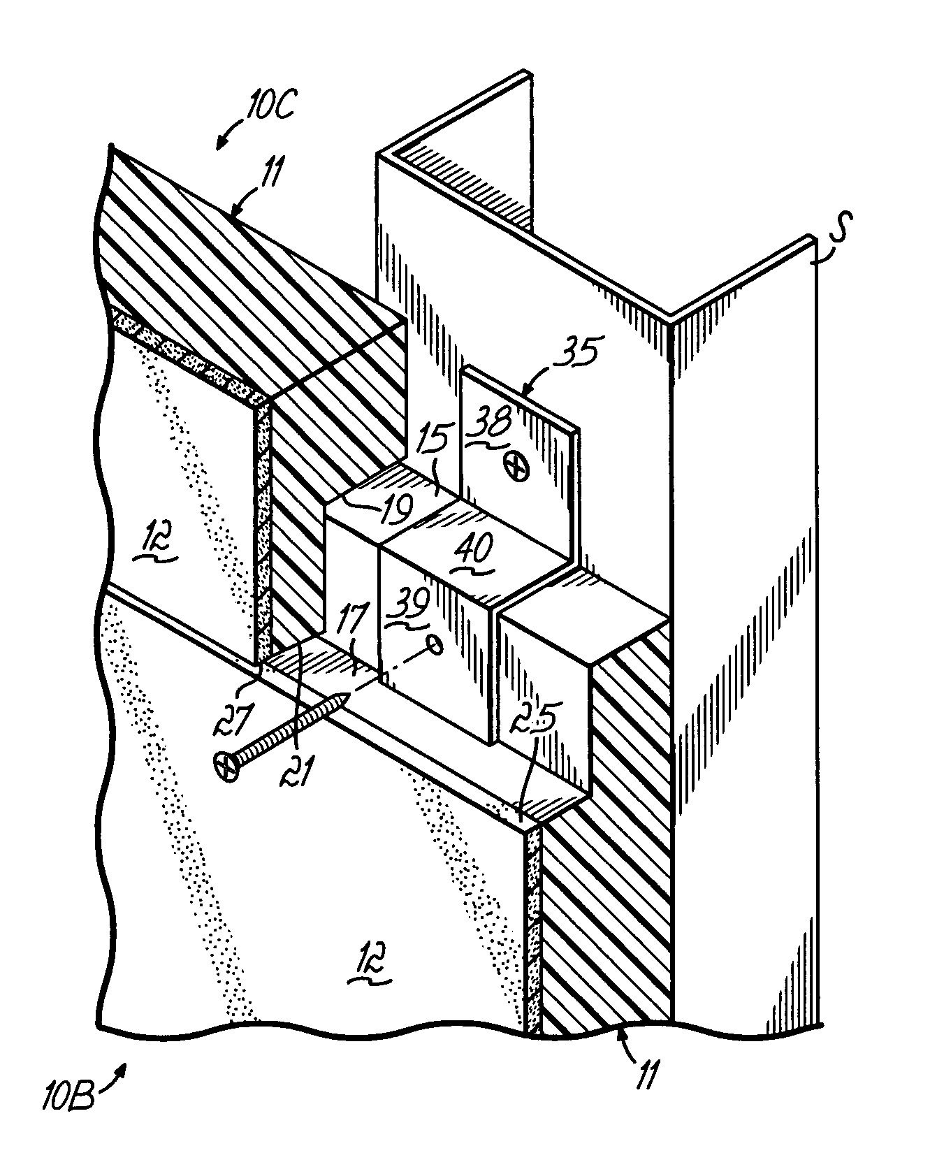
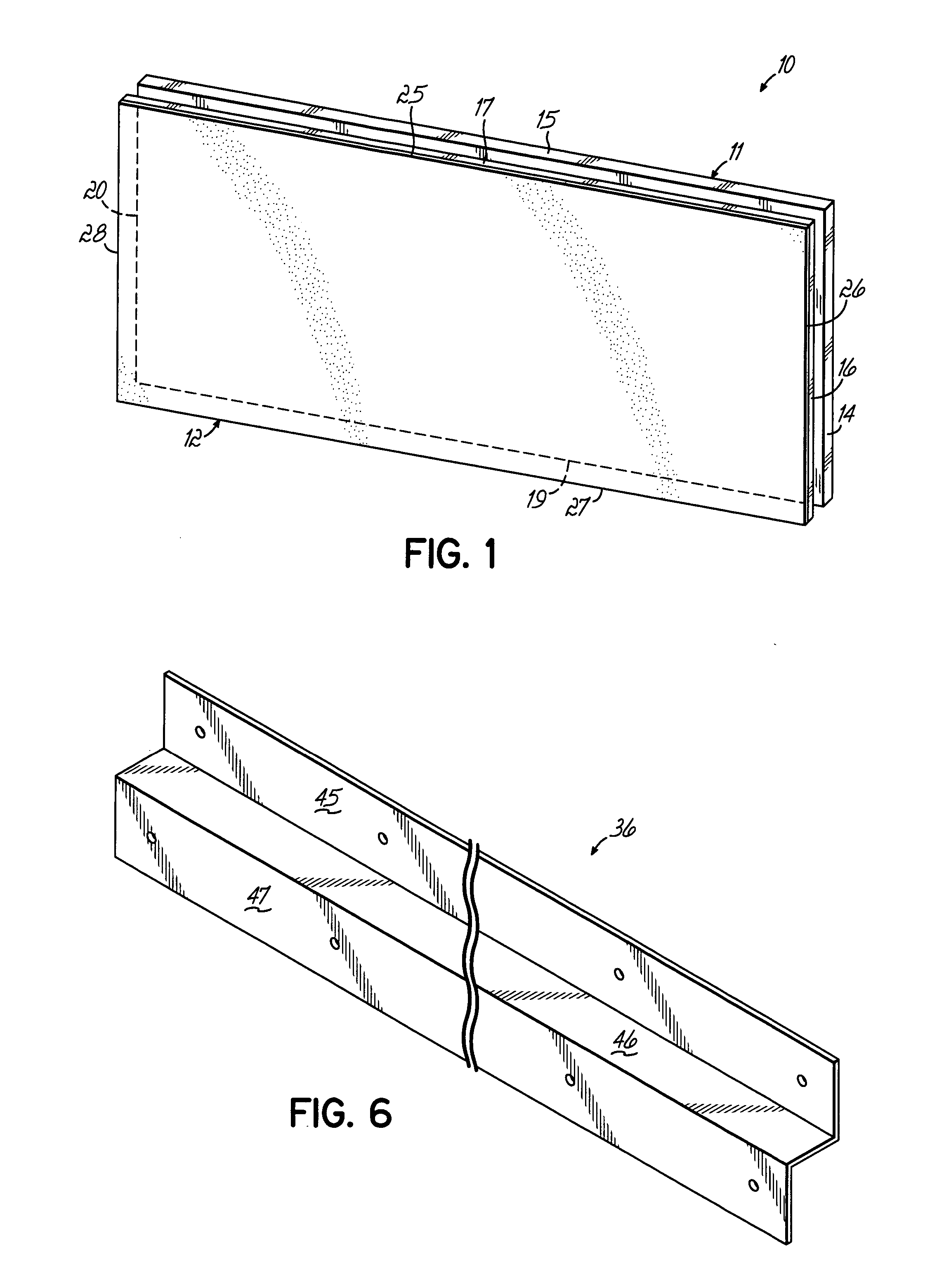
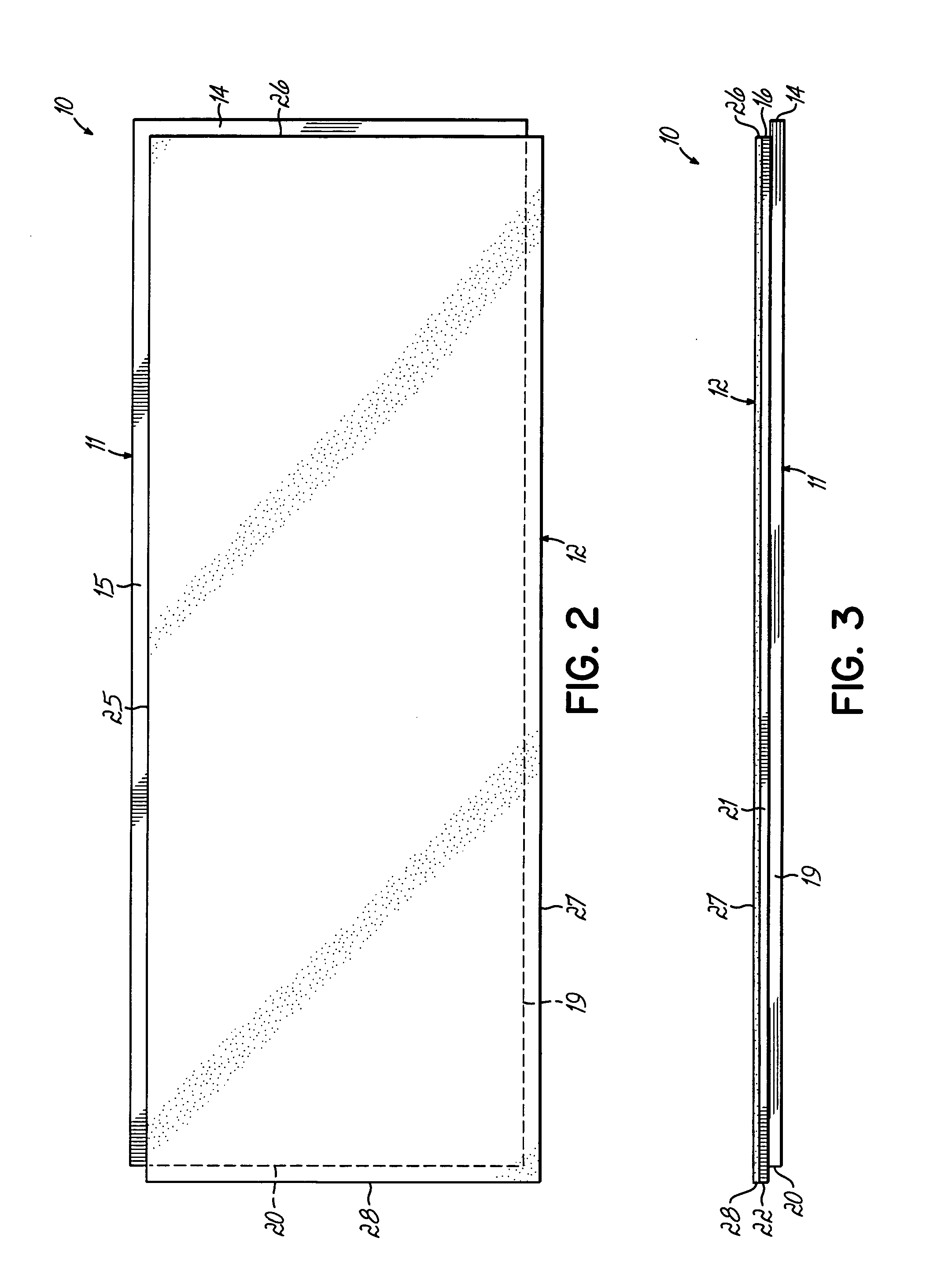
[0024] Turning now to the drawings, there is shown therein an insulated sheathing panel 10, according to one embodiment of the invention. Panel 10 has two primary components, an insulating member 11 and a facing 12.

[0025] Insulating member 11 is preferably comprised of a polystyrene foam, of either expanded or extruded manufacture, such as that polystyrene manufactured by Dow Chemical Company of Midland, Mich. Any suitable insulating material providing insulation, moisture resistance, workability and adhesive compatibility with facing 12, all as will be described, can be used. Insulating member 11 can be sawn, routed, cut or otherwise shaped as desired.

[0026] Facing 12 preferably comprises a cementitious panel with lightweight aggregate core and with mesh reinforced outer faces, all of known manufacture. One form of such facing is sold by Fin-Pan, Inc. of Hamilton, Ohio under its brand mark, “UTIL-A-CRETE”. Such facing and its manufacture is described in detail in one or more of U...


PUM


Abstract

An insulated sheathing panel comprises an insulating member and a facing. The insulating member has two adjacent edges formed by a portion of its thickness extending beyond two corresponding adjacent edges of said facing. Two other adjacent edges of said insulating member in the said relative thickness portion are recessed within two corresponding edges of said facing. When the panels are applied to a stud wall, their edges are ship-lapped, with edges of the facings in abutted relation so there is not thermal break at the panel seam. “Z”-shaped clips or elongated bars are used to secure panels to the stud wall. The panel facings are finished and no vapor barrier is required. Methods are included.

Description

FIELD OF THE INVENTION [0001] This invention relates to building panels and more particularly to insulating sheathing panels for preferred application to stud defined walls of metal or wood, or to existing wall facings. BACKGROUND OF THE INVENTION [0002] Structural insulated wall panels of the type having a foam insulation laminated between two fiberglass mesh reinforced facing panels are well known. One such form of structural wall panel is disclosed in U.S. Pat. Nos. 5,992,110 and 6,065,259. The panels of that patent provide the advantage of insulation and structural integrity, however, those panels have certain inherent limitations. For example, present construction techniques and panel integrity practically limit such structural panels to buildings of only one or two stories. Moreover, when the panels are joined, their straight edges abut in a seam. While an elongated or flat H-shaped connection is used at the seam and spans that seam, and while sufficient thermal seals at such ...

Claims


Application Information

Patent Timeline
IPC IPC(8): E04B1/76E04B1/80E04B2/74E04H5/10
CPCE04B1/762E04H5/10E04B1/80
Inventor CRAWFORD, RICHARDS H.
Owner CRAWFORD RICHARDS H
Why Eureka
Try Eureka