Wall Stud with a Thermal Break

a wall stud and thermal break technology, applied in the direction of walls, fireproofing, girders, etc., can solve the problems of insufficient cost-effective means of building energy-efficient structures, difficult to include in a structure designed for lumber studs, and the loss of heat from wall studs, so as to achieve the effect of not increasing installation costs and maintaining structural integrity

Active Publication Date: 2011-10-06
LOCKHART STACY L
View PDF38 Cites 30 Cited by
  • Summary
  • Abstract
  • Description
  • Claims
  • Application Information

AI Technical Summary

Benefits of technology

[0007]An insulated stud provides a thermal break allowing a builder to create an insulating envelope at the exterior or interior of a building. The wall stud with a thermal break can be constructed in the dimension of conventional lumber so installation costs are not increased and structural integrity remains intact. In a preferred embodiment, the subject insulated stud comprises ½ inch of condensed foam insulation sandwiched between a 2×4 and a 2×2 piece of dimensional lumber. The resulting wall stud with a thermal break is the dimension of a conventional 2×6 stud allowing installation of insulation within the wall of the maximum R value. A machine that can make the subject insulated stud is also described.

Problems solved by technology

A source of heat loss is wall studs.
Steel studs however likewise transfer heat and cold.
Steel studs are not the first choice of a “green” builder however and they can be difficult to include in a structure designed for lumber studs.
These too have proved insufficient in providing a cost effective means of building energy efficient structures.

Method used


Image

  • Wall Stud with a Thermal Break
  • Wall Stud with a Thermal Break
  • Wall Stud with a Thermal Break

Examples


Embodiment Construction

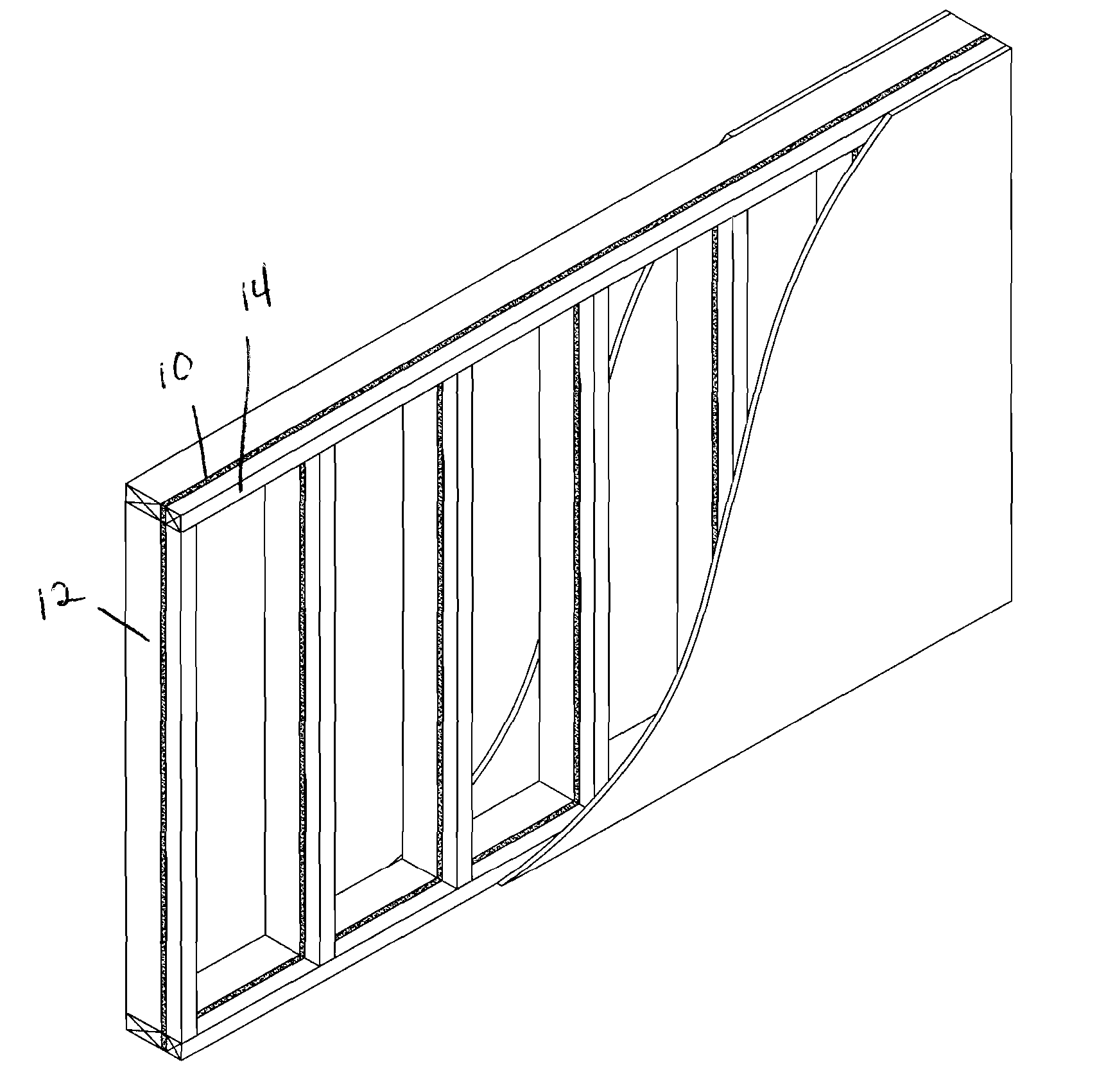
[0038]The invention involves insulated building materials, and in a specific embodiment, an insulated wall stud, that when used in construction provides a thermal envelope at the interior or exterior of the building.

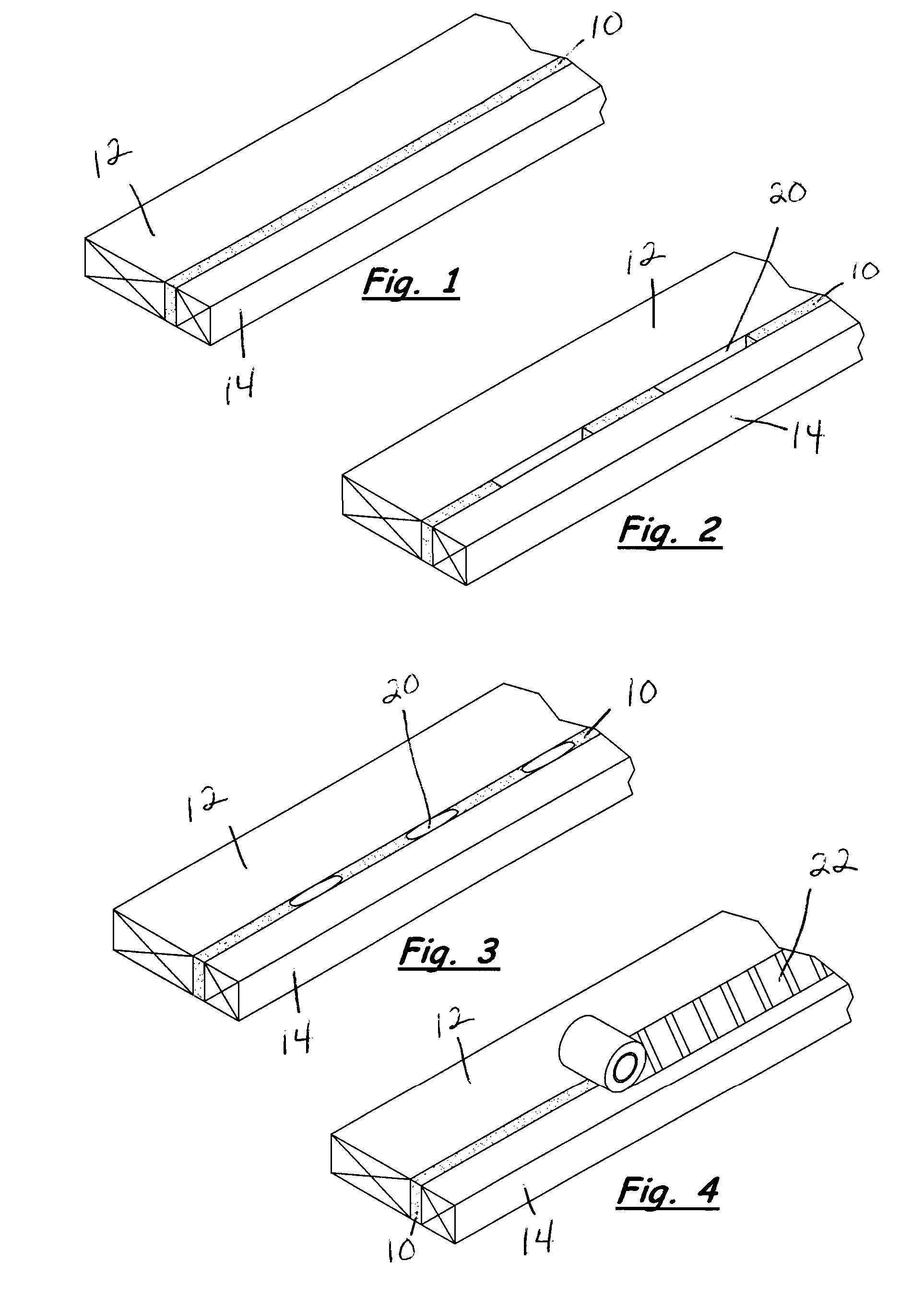
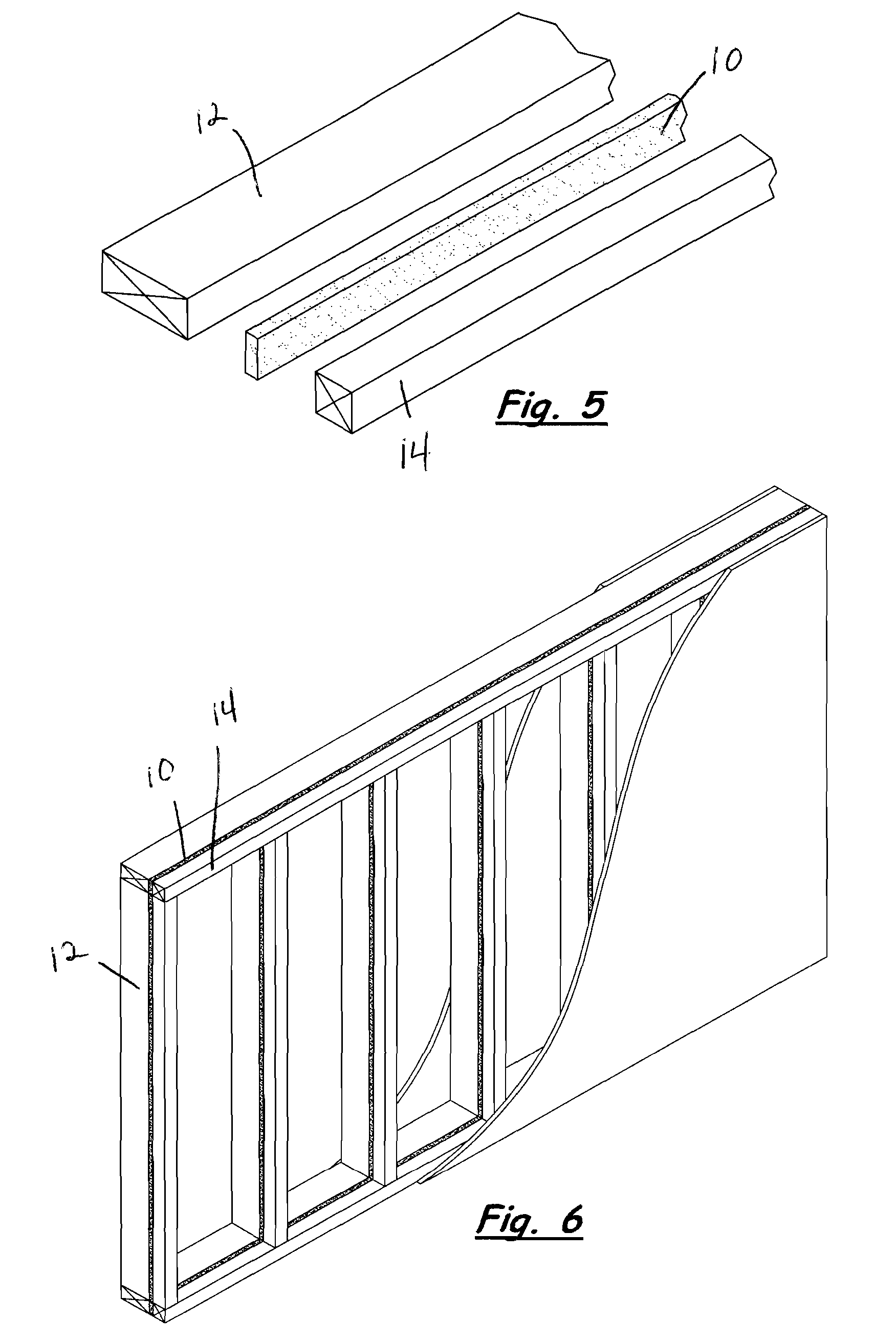
[0039]Preferred embodiments of the insulated building material are shown in the appended figures. The exemplified embodiments show a wall stud. Insulating material 10 is sandwiched between an elongated first structural member 12 and an elongated second structural member 14. In the exemplified embodiments the structural members are pieces of dimensional lumber. Applicant notes however that the subject structural member can be made from post products, composites, or engineered wood products. Further, although the exemplified embodiments show a wall stud, the subject invention can be configured for use as any building material where a thermal break is desired.

[0040]The structural members sandwich insulating material to provide a thermal break across the stud. In the exempli...


PUM


Abstract

Insulating material is sandwiched between one edge of a structural 2×4 and one edge of a structural 2×2 to form a 2×6 wall stud with a thermal break. While shapes, sizes and compositions of the structural members can vary, the insulated wall stud has the advantage of being the size of conventional lumber reducing installation cost.

Description

CROSS-REFERENCE TO RELATED APPLICATIONS[0001]This application claims the benefits of U.S. Provisional Application No. 61 / 319,292, filed Mar. 31, 2010, and U.S. Provisional Application No. 61 / 324,826, filed Apr. 16, 2010, the disclosures of which are hereby incorporated by reference in their entirety including all figures, tables and drawings.STATEMENT REGARDING FEDERALLY SPONSORED RESEARCH OR DEVELOPMENT[0002]Not applicableREFERENCE TO SEQUENCE LISTING, A TABLE, OR A COMPUTER PROGRAM LISTING COMPACT DISC APPENDIX[0003]Not applicableBACKGROUND OF THE INVENTION[0004]Building “green” not only means using recyclable and sustainable materials, it also means building the most cost effective and energy efficient buildings possible. Sustainable materials include lumber of a smaller diameter or composite materials. Building an energy efficient home requires using as much insulation as possible and reducing heat loss. A source of heat loss is wall studs. The wall studs in a home or building t...

Claims


Application Information

Patent Timeline
Patent Type & Authority Applications(United States)
IPC IPC(8): E04B1/94E04C3/29B05B1/00B05C11/00B05C13/00
CPCE04B2/7412E04C3/36E04B2/7457E04B2/7411
Inventor LOCKHART, STACY L.
Owner LOCKHART STACY L
Why Eureka
Try Eureka