Thermal break bracket for a support frame of covering elements

a technology of supporting frame and covering element, which is applied in the direction of structural elements, building components, building reinforcements, etc., can solve the problems of low elasticity, high production cost, and difficulty in absorbing vibrations and adapting to the different working tolerances

Inactive Publication Date: 2015-10-29
AV_NEW
View PDF0 Cites 28 Cited by
  • Summary
  • Abstract
  • Description
  • Claims
  • Application Information

AI Technical Summary

Benefits of technology

[0030]Thanks to the T-shaped configuration, the second walls of the polymer component of the bracket define an assembly position of the second metal component distanced from the wall of the building, so as to eliminate any point of contact between the wall of the building,

Problems solved by technology

Making attachment apparatuses entirely of metal has various disadvantages, including: a high thermal bridge between the surface of the building to be insulated and the metal structure of the support frame, and therefore between the inside and the outside of the building; low elasticity, so that it is difficult to absorb the v

Method used


Image

  • Thermal break bracket for a support frame of covering elements
  • Thermal break bracket for a support frame of covering elements
  • Thermal break bracket for a support frame of covering elements

Examples


Embodiment Construction

[0042]We shall now refer in detail to the various forms of embodiment of the present invention, of which one or more examples are shown in the attached drawing. Each example is supplied by way of illustration of the invention and shall not be understood as a limitation thereof. For example, the characteristics shown or described insomuch as they are part of one form of embodiment can be adopted on, or in association with, other forms of embodiment to produce another form of embodiment. It is understood that the present invention shall include all such modifications and variants.

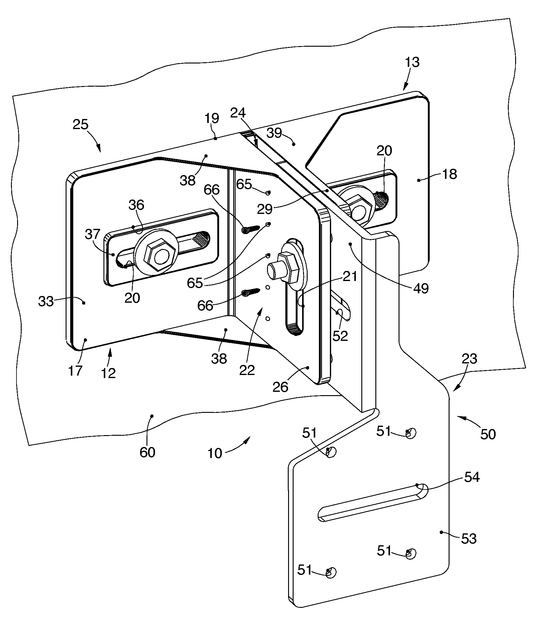
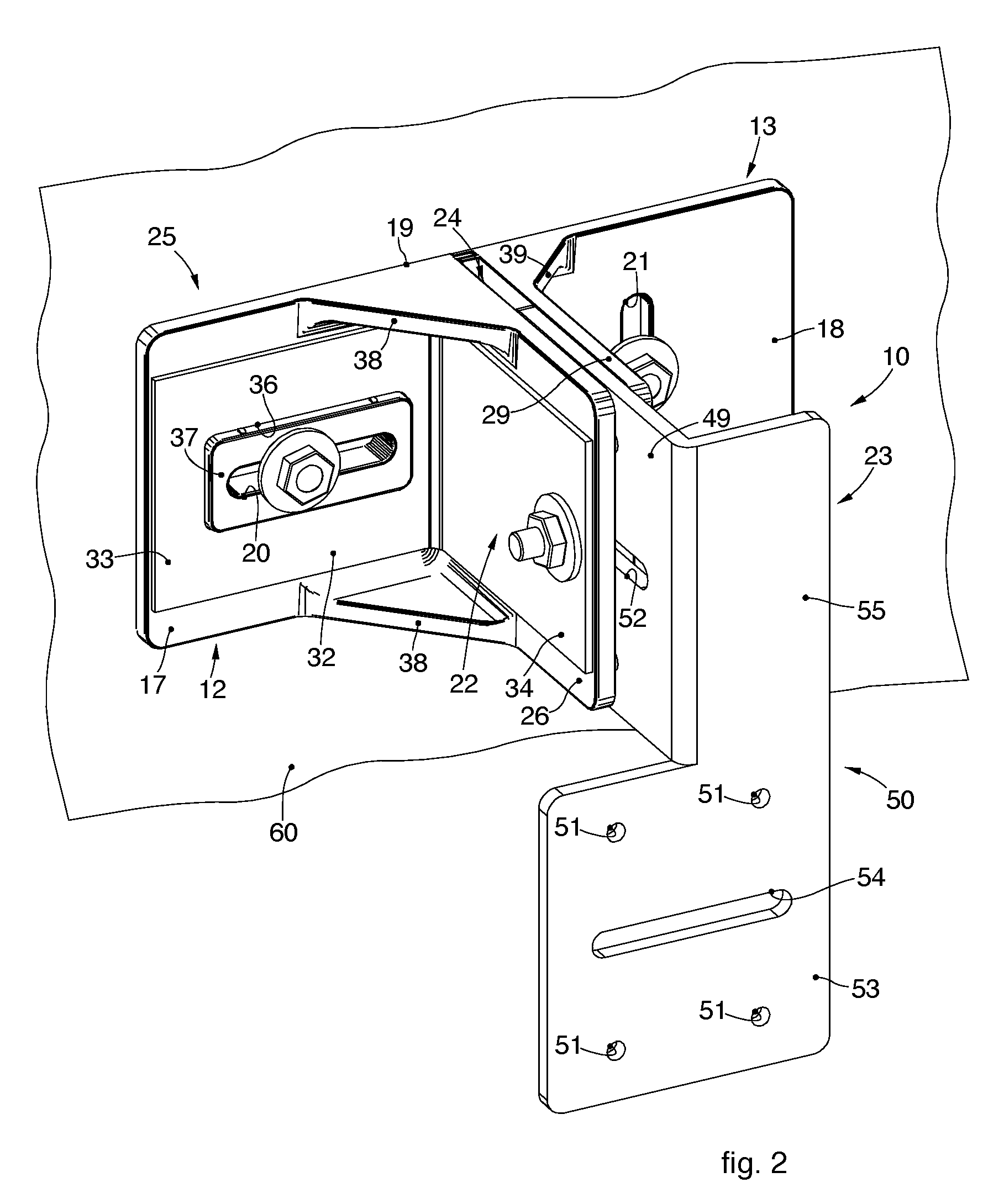
[0043]FIGS. 1-7 are used to describe forms of embodiment of a thermal break bracket 10 used to attach a support frame 11 to an attachment wall 60, shown schematically in FIGS. 2 and 3.

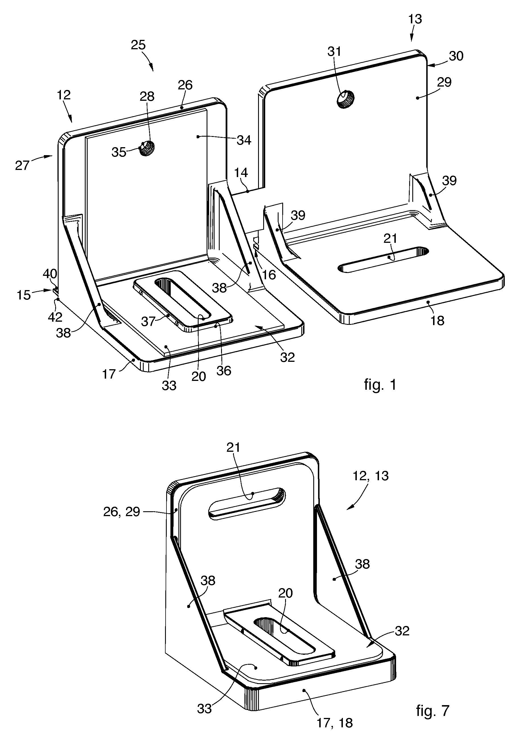
[0044]The thermal break bracket 10 has a first component 25 (FIGS. 1, 7) made at least partly, advantageously wholly, of polymer material, such as polyamide for example, obtainable by molding or other suitable working process.

[0...


PUM


Abstract

Thermal break bracket to attach a support frame to an attachment wall, made of polymer material and comprising two parts, first and second, in which the first part performs the function of a transverse adjustment element, while the second part performs the function of a vertical adjustment element with respect to the attachment wall.

Description

FIELD OF THE INVENTION[0001]The present invention concerns a thermal break bracket for a support frame of covering elements of the modular type, such as bricks, panels, plates, tiles or suchlike, substantially of any size and material, used mainly in the building sector, both public and private and street furniture.BACKGROUND OF THE INVENTION[0002]Support frames are known for external covering elements that are versatile, simple and practical to use, and are designed to create, quickly and at low cost, covering structures and facades of buildings to be applied to the walls.[0003]The covering elements normally have the shape of tiles or slabs of a geometric shape, normally but not necessarily square, and can be made of various materials, including ceramic, marble, terracotta, wood, glass or other.[0004]The support frames normally have a plurality of rapid clamping elements, provided with fins which cooperate by interference with corresponding grooves provided along the edges of the c...

Claims


Application Information

Patent Timeline
IPC IPC(8): E04B1/41
CPCE04B1/40E04B2001/7679E04B2001/405E04F13/0807E04F13/0808E04B2/7411E04B2001/389E04B1/388
Inventor TESSADORI, ANDREA
Owner AV_NEW
Why Eureka
Try Eureka