Implantable medical device constraint and deployment apparatus

a technology for implantable medical devices and devices, applied in the direction of prosthesis, manufacturing tools, blood vessels, etc., can solve the problems of limiting the size and type of implantable devices that it can effectively constrain and deploy, affecting the deployment efficiency of the device, etc., to achieve the effect of simple, accurate and reliable device deploymen

Active Publication Date: 2015-09-10
WL GORE & ASSOC INC
View PDF13 Cites 18 Cited by
  • Summary
  • Abstract
  • Description
  • Claims
  • Application Information

AI Technical Summary

Benefits of technology

[0008]The present invention provides a scalable delivery system that protects medical devices during delivery in a body while providing simple, accurate, and reliable device deployment. The delivery system is configured so ...

Problems solved by technology

The use of everting sleeves as described in these references has many advantages, but there are limitations on length, geometry, tensile strength, and other properties of the devices that can be effectively mounted in and deployed from many of these sleeves.
Additionally, prior everting sleeves deployment apparatus have been challenged to balance adequate constraint of implantable devices prior to deployment against accurate and easy deployment of the implantable devices in the desired location in the body.
While this apparatus works very well, it also has limitations on the size and types of implantable devices that it can effectively constrain and deploy.
One concern with this and other fiber constraints is that fibrous covers may not smoothly mount and/or deploy from certain device...

Method used


Image

  • Implantable medical device constraint and deployment apparatus
  • Implantable medical device constraint and deployment apparatus
  • Implantable medical device constraint and deployment apparatus

Examples


Embodiment Construction

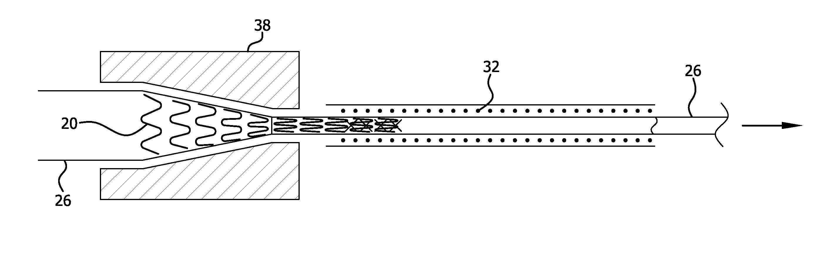
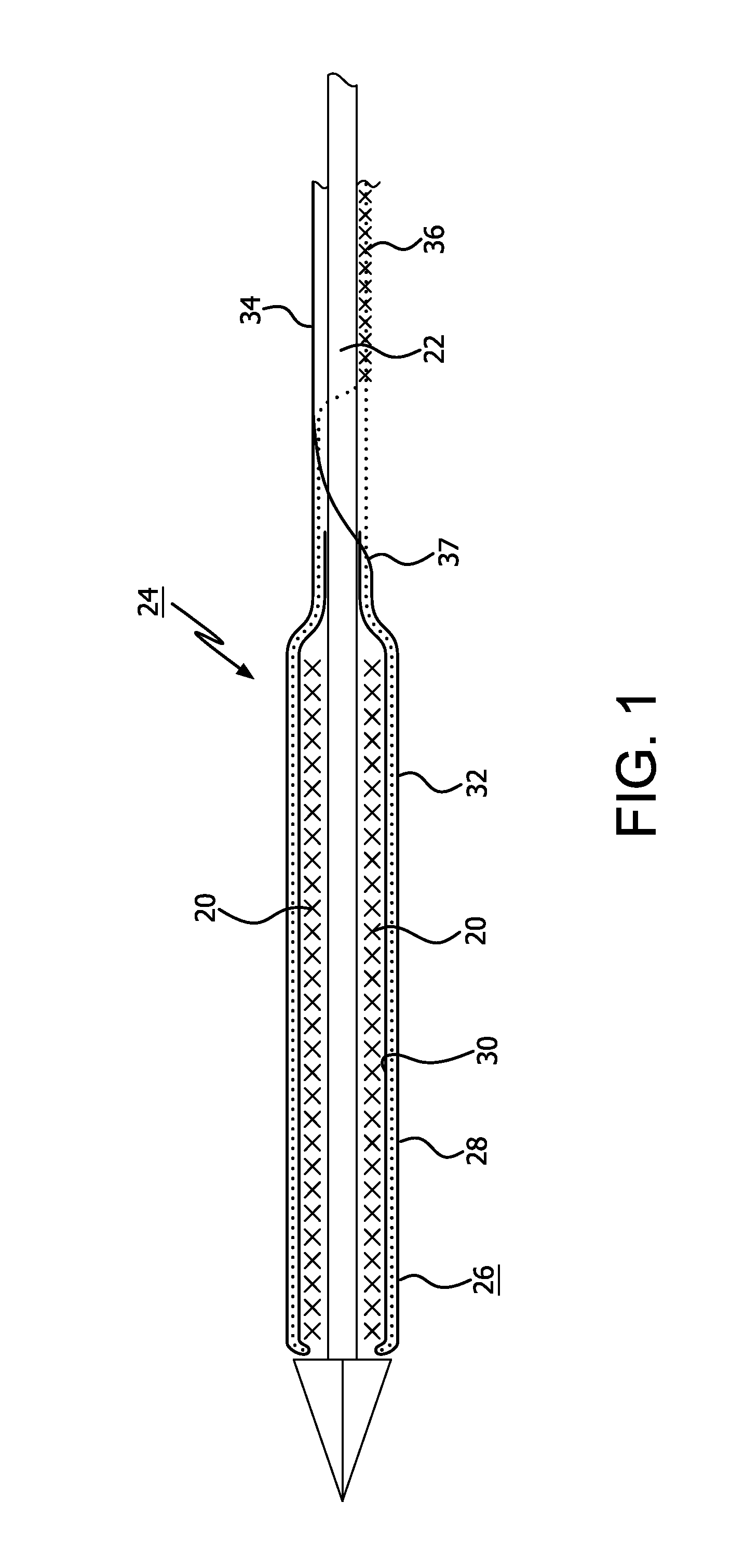
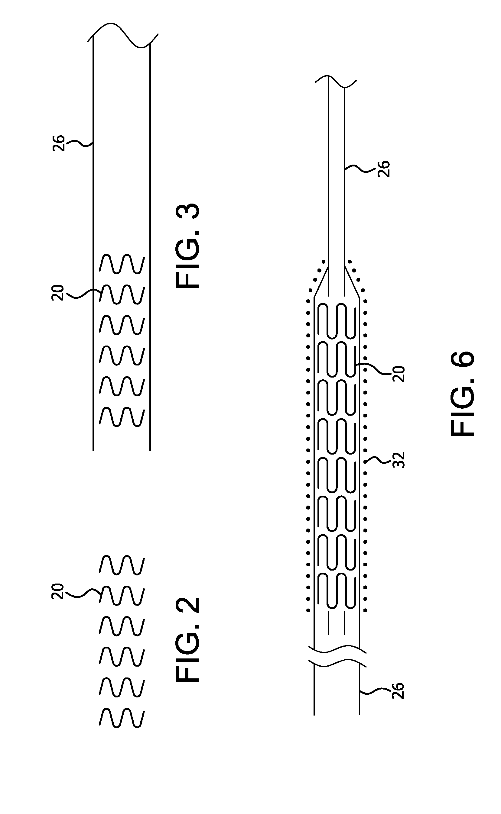
[0031]The present invention provides improved apparatus to constrain, deliver, and / or deploy a medical device. The invention may be used in conjunction with a wide variety of devices that may be temporarily or permanently deployed in a patient, including without limitation stents, stent-grafts, balloons, filters, traps, occluders, devices for delivering drugs or other therapeutic substances or treatments, and the like. As such, the terms “medical device” and “implantable device” in the present application are intended to be broadly construed to encompass any device that is temporarily or permanently placed in a body.

[0032]The apparatus of the present invention may be employed to deliver self-expanding devices, devices that are expandable by balloons or other means, self-expanding / expandable hybrid devices, and devices that are not intended to change dimensions in situ.

[0033]Particular embodiments of the present invention are described below by way of illustration. It should be under...


PUM

PropertyMeasurementUnit
Lengthaaaaaaaaaa
Forceaaaaaaaaaa
Diameteraaaaaaaaaa

Abstract

An implantable medical device deployment system is disclosed that employs both a sheath element and a constraint member to protect implantable medical devices during delivery in a body while providing simple, accurate, and reliable device deployment. The delivery system is configured so that loading and deployment forces are not directly related to device diameter, length, or design, thus allowing a more universal delivery system across various delivered device configurations and product lines. The deployment system can provide numerous benefits, include better protection for drug-coated implantable devices.

Description

BACKGROUND OF THE INVENTION[0001]1. Field of the Invention[0002]The invention relates to apparatus and methods for the delivery and deployment of implantable medical devices.[0003]2. Discussion of the Related Art[0004]With the growing proliferation of sophisticated implantable medical devices and more advanced treatment apparatus, and particularly medical devices and treatments that are delivered and deployed through minimally invasive procedures such as stents, stent-grafts, balloons, filters, occluders, and the like, there has been a growing interest in finding improved devices and methods to effectively constrain, deliver, and / or deploy such devices and treatment apparatus.[0005]Examples of previous devices and methods for delivering and deploying such devices include the use of everting sleeves to constrain the implantable device and then deploy the devices in a controlled manner in situ, such as the devices described in U.S. Pat. No. 7,285,130 to Austin, US Application 2008-028...

Claims


Application Information

Patent Timeline
IPC IPC(8): A61F2/95A61F2/01A61F2/966A61B17/12
CPCA61F2/95A61B17/12022A61F2/01A61F2002/011A61F2002/9522A61B2017/12054A61F2/966A61B17/0057A61B17/12109A61B17/12122A61F2/07A61F2/82A61F2/856A61F2/90A61B2017/00623A61B2017/00601A61B2017/00592A61B2017/00597A61B2017/00575A61B2017/00579A61B17/12177A61F2002/9505A61F2002/9511A61F2/954A61F2002/016A61F2/011A61F2/9525A61F2250/0067Y10T29/49872A61F2/9522A61F2/9517A61F2/962
Inventor IRWIN, CRAIG W.SILVERMAN, JAMES D.
Owner WL GORE & ASSOC INC
Why Eureka
Try Eureka