Dispenser for discharging pharmaceutical liquids

Pending Publication Date: 2022-06-16
APTAR RADOLFZELL
View PDF0 Cites 0 Cited by
  • Summary
  • Abstract
  • Description
  • Claims
  • Application Information

AI Technical Summary

Benefits of technology

The invention relates to a droplet dispenser that can deliver pharmaceutical liquid in the form of single droplets. The dispenser has a means of droplet formation, which helps the liquid to form droplets before they become detached from the formation area. The delivery valve of the dispenser is designed to open at a positive pressure of at least 0.3 bar, but can also open at lower pressures. The dispenser also has a removable dispenser cap that can be placed onto the dispenser housing and removed therefrom for use. The cap is ventilated and has a sterile filter to prevent the introduction of microbes. It also has an integrated pad to absorb and / or decontaminate any liquid residue that may remain downstream of the delivery opening.

Problems solved by technology

However some aspects of the dispensers described therein are disadvantageous.
For instance, it can be difficult for the user, in the case of actuation by thumb, to achieve controlled depression of the displacement of the actuating handle therein.
The first use is also made difficult in that, as supplied, too much air is present in the pump chamber and the discharge channel, and the delivery valve therefore has to open at a very low positive pressure in order to enable the air to be driven out by initial actuation.
Furthermore, specifically droplet dispensers require very accurate matching of all fluid-guiding components, which makes it difficult to adapt such a dispenser to customer wishes, i.e. especially to a design typical on the market for a manufacturer of pharmaceutical liquids with regard to shape and color.
The rocking movement of the rocker button results in the at least partial displacement of the pump chamber wall, which increases the pressure in the pump chamber and pushes liquid in the direction of the delivery opening.
As a result, however, the channel section assumes quite a large volume, which complicates the first use of the dispenser since the air first has to be driven out of this channel section on first use.

Method used


Image

  • Dispenser for discharging pharmaceutical liquids
  • Dispenser for discharging pharmaceutical liquids
  • Dispenser for discharging pharmaceutical liquids

Examples


Embodiment Construction

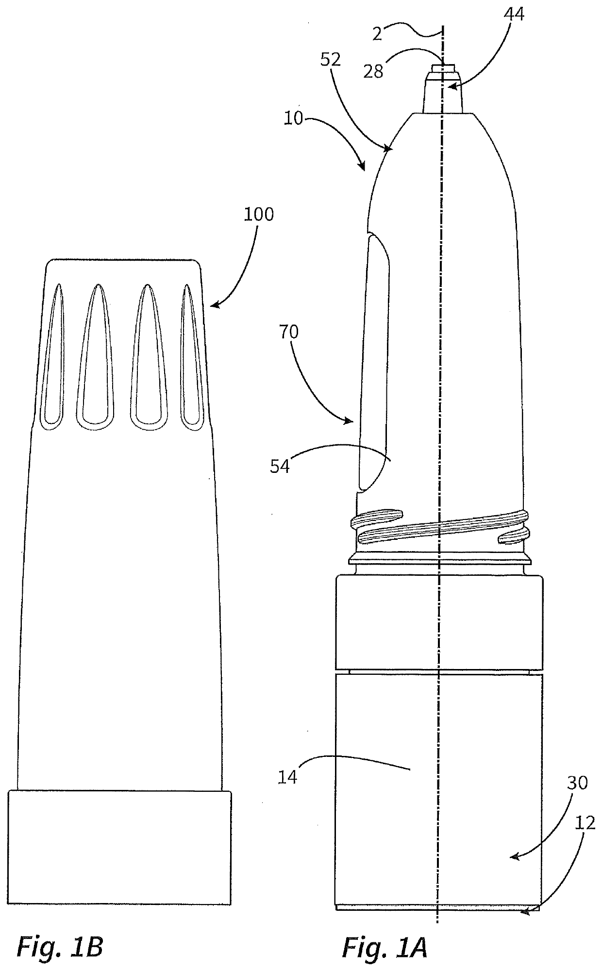
[0051]FIGS. 1A and 1B show a first working example of the dispenser of the invention in a non-section diagram together with its dispenser cap. The main unit of this configuration of the dispenser shown in FIG. 1A has an elongate housing composed of various housing constituents 30, 12, 52, 44 and aligned in a main direction of extension 2. As described hereinafter, a pump device 16 is provided within the housing, by means of which liquid can be conveyed from a liquid reservoir 14 at a proximal end of the dispenser 10 to a delivery opening 28 at a distal end of the dispenser 10. For actuation of the pump device 16, an actuating button 70 is provided.

[0052]The dispenser cap 100 shown in FIG. 1B can be placed by means of a thread onto the housing of the dispenser 10.

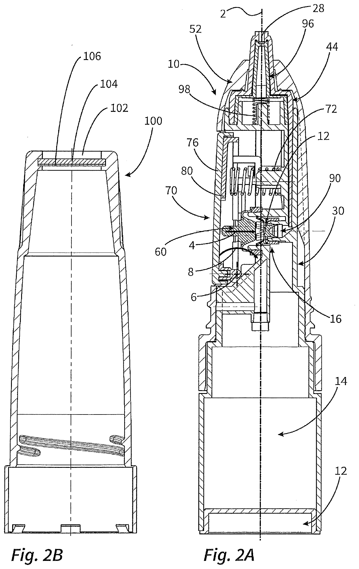
[0053]FIGS. 2A and 2B show the main unit of the dispenser 10 and the dispenser cap 100 in cross section view.

[0054]The main elements are to be described first with reference to this drawing.

[0055]As apparent in FIG. 2A, the ...


PUM


Abstract

A dispenser for discharging pharmaceutical liquids, in particular in the form of individual drops. Such a dispenser is designed as a side-actuation dispenser with an actuation button on the dispenser in the region of a lateral surface of the housing and has a liquid store, a pump device with a pump chamber which has a variable volume, and a dispensing opening for dispensing the liquid. The actuation button is a spring-loaded toggle switch, the volume of the liquid channel is reduced using an insert, and a special housing design is provided for the purpose of adapting the dispenser to the customer's needs.

Description

AREA OF APPLICATION AND PRIOR ART[0001]The invention relates to a dispenser for discharge of pharmaceutical liquids, especially for the dropwise discharge of pharmaceutical liquids in the form of individual droplets.[0002]A dispenser of the generic type has a liquid reservoir, a pump device having a volumetrically variable pump chamber, and a delivery opening for delivery of the liquid. By means of the pump device, liquid can be conveyed to the delivery opening. The dispenser is designed as a side-actuation dispenser. What this means is that the dispenser has an elongate housing aligned in a main direction of extension and the delivery opening is provided at a distal end of the dispenser, with an actuating button provided for actuation of the pump device in the region of an outer surface of the housing at the side of the dispenser. The handling is typically effected in such a way that the outer surface of the housing is gripped, and the actuating button is actuated by thumb.[0003]DE...

Claims


Application Information

Patent Timeline
IPC IPC(8): B05B11/00
CPCB05B11/0032B05B11/3064B05B11/3028A61J1/20A61F9/0008B05B11/00444B05B11/0067B05B11/103B05B11/1061B05B11/1064B05B11/1074B05B11/1028
Inventor GREINER-PERTH, JÜRGENHERZ, ANDI
Owner APTAR RADOLFZELL
Why Eureka
Try Eureka