Rotational magnetic electrical generating device

a technology of rotating magnetic and electrical generating device, which is applied in the direction of dynamo-electric components, dynamo-electric machines, electrical apparatus, etc., can solve the problems of heat generation and wear at the components

Inactive Publication Date: 2007-05-15
CONTIEMPO ENERGY
View PDF20 Cites 21 Cited by
  • Summary
  • Abstract
  • Description
  • Claims
  • Application Information

AI Technical Summary

Benefits of technology

[0011]Electrical generating devices using permanent magnets are known in the prior art, as demonstrated by the several patents disclosed and many others of similar design and function. Over time, permanent magnets have become more sophisticated and have even been patented as new inventions, as indicated in the neodymium magnet. These magnet have been incorporated into new generating devices. However, these devices also have mechanical components that create friction causing the generation of heat, and also wear at the components where the friction occurs. The current device eliminates contact between moving parts during the generation of electromagnetic AC current of the prior art by placing a magnetic field between a rotating magnetic cylinder in a vacuum environment enclosed structure, the rotating magnetic cylinder being the only moving part within the entire device and not in contact with any other component in the device.

Problems solved by technology

However, these devices also have mechanical components that create friction causing the generation of heat, and also wear at the components where the friction occurs.

Method used


Image

  • Rotational magnetic electrical generating device
  • Rotational magnetic electrical generating device
  • Rotational magnetic electrical generating device

Examples


Embodiment Construction

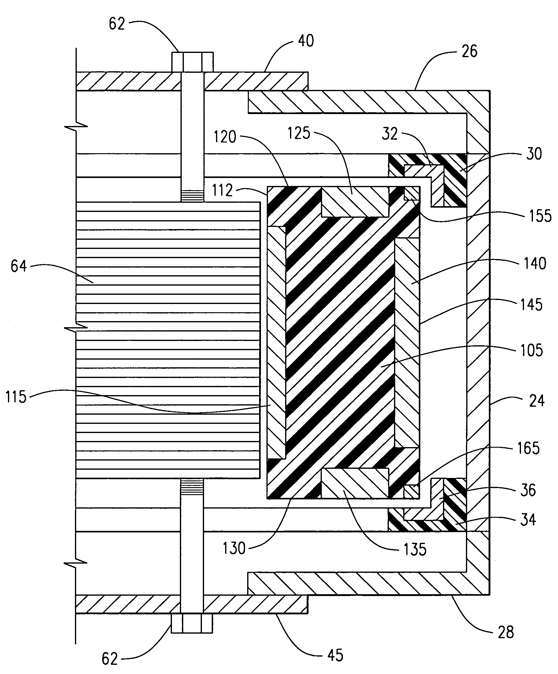
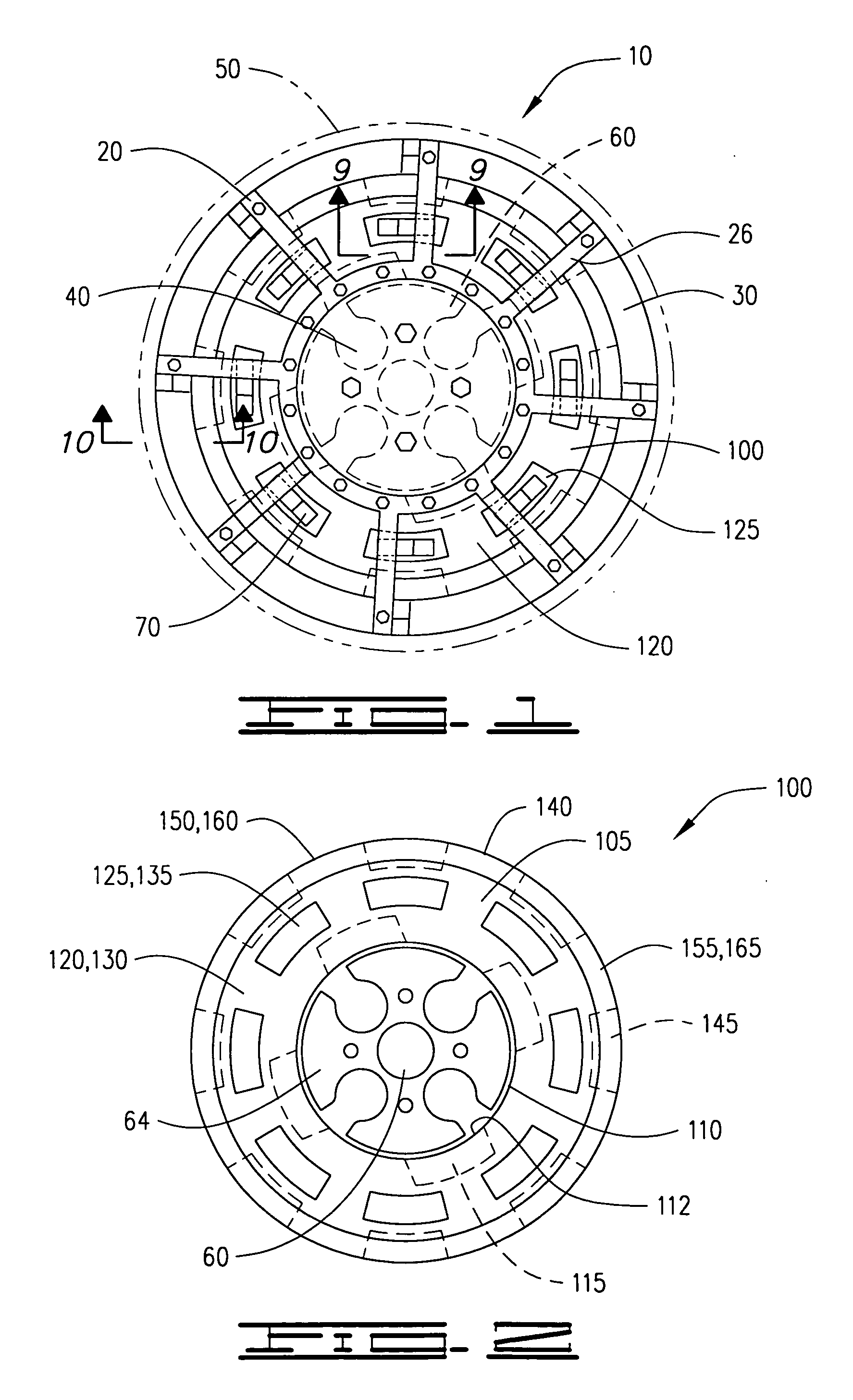
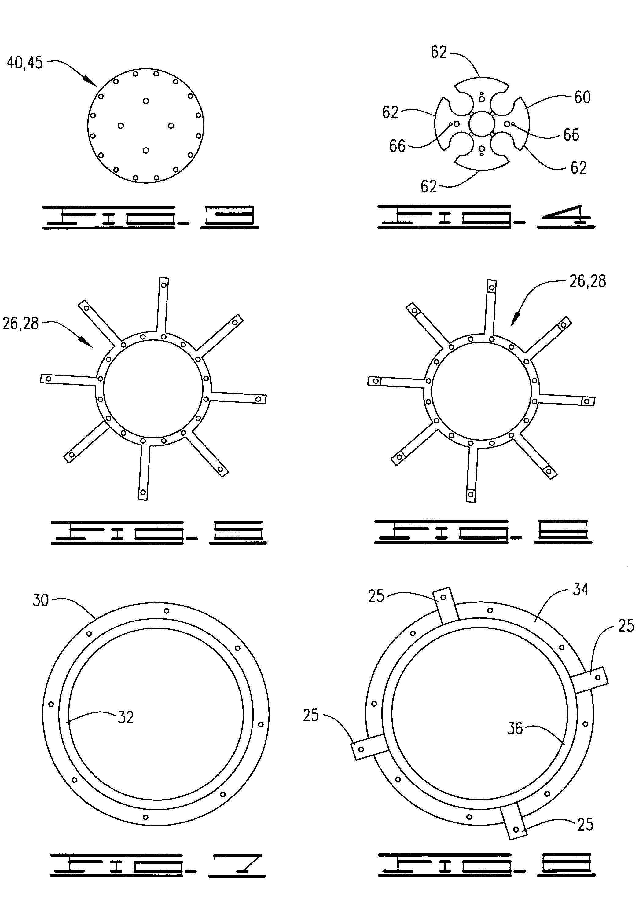
[0031]A rotary electro-magnetic generating device 10, shown in FIGS. 1–16 of the drawings, for the production and generation of alternating electrical current (AC) having but one single moving component without contact friction with any other components comprises a fixed support frame 20 within which is suspended a central rotational magnetic cylinder 100 between an upper and lower magnetic field, the central rotational magnetic cylinder 100, rotating between the frictionless, non-contact magnetic fields.

[0032]The central rotational magnetic cylinder 100, shown in FIGS. 1, 2, 9–14 and 16, comprises a supporting body 105 made of a non-conducting material and having an inner cylindrical cavity 110 defined therein, the inner cylindrical cavity 110 having an inner surface 115 having a set of evenly spaced alternate polarity embedded inner magnets 115, an upper surface 120 having a set of evenly spaced alternate polarity embedded upper magnets 125, a lower surface 130 having a set of eve...


PUM


Abstract

A rotational magnetic electrical generating device produces an alternating electrical current generated by a central rotational magnetic cylinder with an inner cavity having an central fixed coil operated by a DC current providing a driving rotational force upon a plurality of embedded neodymium magnets within the inner cavity of the central rotational magnetic cylinder, the central rotational magnetic cylinder having an upper outer margin with an upper magnetic ring and a lower outer margin having a lower magnetic ring, the two magnetic rings suspending the central rotational magnetic cylinder between two fixed magnetic fields supported by a frame member, the central rotational magnetic cylinder further having an outer perimeter surface embedded with a plurality of neodymium alloy magnets equally sized and spaced apart, a lower surface embedded with a plurality of neodymium alloy magnets equally sized and spaced apart, and an upper surface embedded with a plurality of neodymium alloy magnets equally sized and spaced apart. A plurality of alternate wound electrical stators are suspended above the upper surface, below the lower surface and around the outer perimeter surface of the central rotational magnetic cylinder, supported by the frame member while insulated from the frame member, each electrical stator connected to external leads to transmit alternating current generated by the spinning central rotational magnetic cylinder, the entire device enclosed within a vacuum.

Description

CROSS REFERENCE TO RELATED APPLICATIONS[0001]NoneI. BACKGROUND OF THE INVENTION[0002]1. Field of Invention[0003]A rotational magnetic electrical generating device produces an alternating electrical current generated by a central rotational magnetic cylinder with an inner cavity having an central fixed coil operated by a DC current providing a driving rotational force upon a plurality of embedded neodymium magnets within the inner cavity of the central rotational magnetic cylinder, the central rotational magnetic cylinder having an upper outer margin with an upper magnetic ring and a lower outer margin having a lower magnetic ring, the two magnetic rings suspending the central rotational magnetic cylinder between two fixed magnetic fields supported by a frame member, the central rotational magnetic cylinder further having an outer perimeter surface embedded with a plurality of neodymium alloy magnets equally sized and spaced apart, a lower surface embedded with a plurality of neodymi...

Claims


Application Information

Patent Timeline
Patent Type & Authority Patents(United States)
IPC IPC(8): H02K21/00H02K7/09
CPCH02K7/09H02K21/12
Inventor MCDONALD, DONNIE PAT
Owner CONTIEMPO ENERGY
Why Eureka
Try Eureka