Self-attaching fastener systems

a fastener and self-attaching technology, applied in the direction of threaded fasteners, screwing, manufacturing tools, etc., can solve the problems of reducing bearing area, strip may not fully engage the stop, and the bore may not be accurately centered in the pilot portion, so as to prevent the movement of the fastener, eliminate the damage to the thread cylinder, and accurately locate the nut bore in the fastener

Inactive Publication Date: 2008-09-23
PENN AUTOMOTIVE INC
View PDF62 Cites 24 Cited by
  • Summary
  • Abstract
  • Description
  • Claims
  • Application Information

AI Technical Summary

Benefits of technology

[0011]In the most preferred embodiment of this invention, the bottom wall of the wire groove or grooves includes a plurality of spaced pockets. As used herein, the term “pockets” may include either depressions or upstanding ribs, defining pockets therebetween. The continuous frangible wire is then deformed against the bottom wall of the wire groove, filling the pockets, and preventing movement of the fasteners on the wires.
[0012]The method of feeding a preoriented strip of fasteners to an installation head and preoriented fastener strip of this invention also eliminates damage to the thread cylinder. The method of forming a preoriented strip of fasteners of this invention includes forming a plurality of discreet self-attaching fasteners, preferably of the type described above, wherein each of the fasteners includes a projecting pilot portion, a flange portion on opposed sides of the pilot portion having a panel receiving surface adjacent the pilot portion and side surfaces. The method then includes forming a plurality of preferably equally spaced abutment surfaces on at least one of the sides of each of the fasteners, orienting the fasteners in end to end relation, preferably in nearly abutting relation, and then interconnecting the fasteners by a frangible connector element forming a preoriented strip of fasteners having abutment surfaces on at least one side of the preoriented fastener strip. The preoriented fastener strip is then fed to an installation head by receiving a driving member seriatim in the spaced abutment surfaces and moving the driving member to drive the strip of preoriented fasteners to the installation head. In the preferred embodiment, the abutment surfaces are equally spaced notches or grooves in the side wall of the fasteners. This method thus eliminates contact of the driving member with the bore of the fasteners.
[0013]Another advantage of the method of forming and feeding a preoriented strip of fasteners of this invention is that the abutment surfaces may be formed in the rolled metal strip from which the fasteners are formed and used to accurately locate the nut bore in the fasteners formed from the strip. This method includes forming a continuous metal strip having the cross-section of the self-attaching fasteners to be formed including a continuous central projecting pilot portion and flange portions on opposed sides of the pilot portion, wherein the flange portions include a bearing face spaced below the end face of the pilot portion and side faces. The method of forming self-attaching female fasteners of this invention then includes forming a plurality of equally spaced notches in at least one side face of the continuous strip, locating the continuous strip opposite a cylindrical punch by receiving a locating member in one of the notches and moving the punch to punch a cylindrical bore in the strip, then moving the strip to successively receive the locating member in a second notch in the strip opposite the punch to punch a plurality of equally spaced cylindrical bores in the strip and finally locating the strip opposite a cut-off tool by receiving a locating member in a notch in the strip and then moving the cut-off tool to at least partially severe the self-attaching female fasteners from the strip, preferably completely severing the strip to form discreet fasteners. This method assures that the nut bore is accurately located through the pilot portion of each nut, eliminating a problem with the present method of forming self-attaching female fasteners. In the preferred method, the fasteners are completely severed from the strip and the fasteners are then interconnected by frangible connectors as described above.

Problems solved by technology

One problem with this method of forming self-attaching fasteners, particularly in mass production applications, is that the bore may not be accurately centered in the pilot portion because the exact position of the strip is difficult to control.
However, the strip may not fully engage the stop or bounce off the stop.
This is a particular problem in mass production applications because only two bores are punched at a time and therefore the strip must be repeatedly located opposite the punches.
There are several problems associated with the present method of forming a preoriented fastener strip as disclosed in the above referenced U.S. Pat. No. 3,711,931, and the feeder system described above.
First, location of the wires on the rear bearing face of the pierce or clinch nut reduces the bearing area for the punch which installs the fastener in a panel.
Another problem associated with forming a preoriented strip of fasteners as disclosed in the above referenced patent is that the frangible wires interconnecting the self-attaching fasteners may be pulled out of the wire grooves during installation of the fastener in a panel, creating a sharp wire end on the rear surface of the fastener.
Thus, when the frangible wires are severed during the installation process, these sharp wire ends protrude from the wire grooves adjacent the rear bearing surface of the fastener following installation which also creates a potential handling hazard.
Another problem with the method of attaching the self-attaching fasteners in a preoriented fastener strip as disclosed in the above referenced patent is movement of the nuts on the wires prior to and during feeding of the nuts to the installation head which may cause misfeeding.
Finally, another problem with the present method of feeding self-attaching nuts to an installation head is damage to the thread cylinder of the threaded bore through the pilot portion.
The feed pawl may damage the thread cylinder.

Method used


Image

  • Self-attaching fastener systems
  • Self-attaching fastener systems
  • Self-attaching fastener systems

Examples


Embodiment Construction

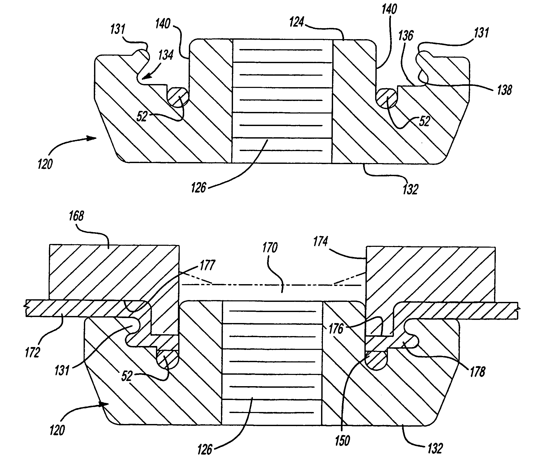
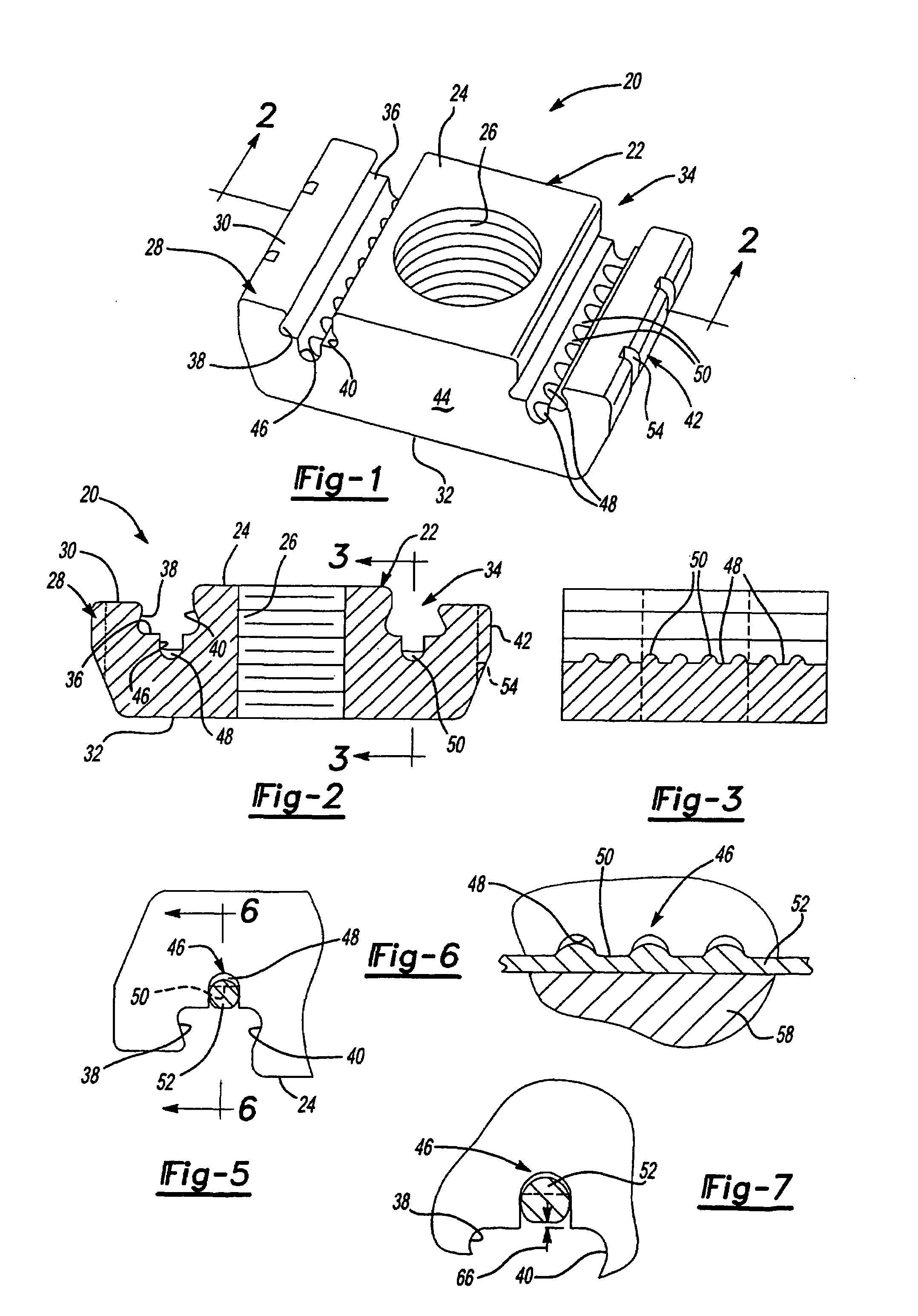
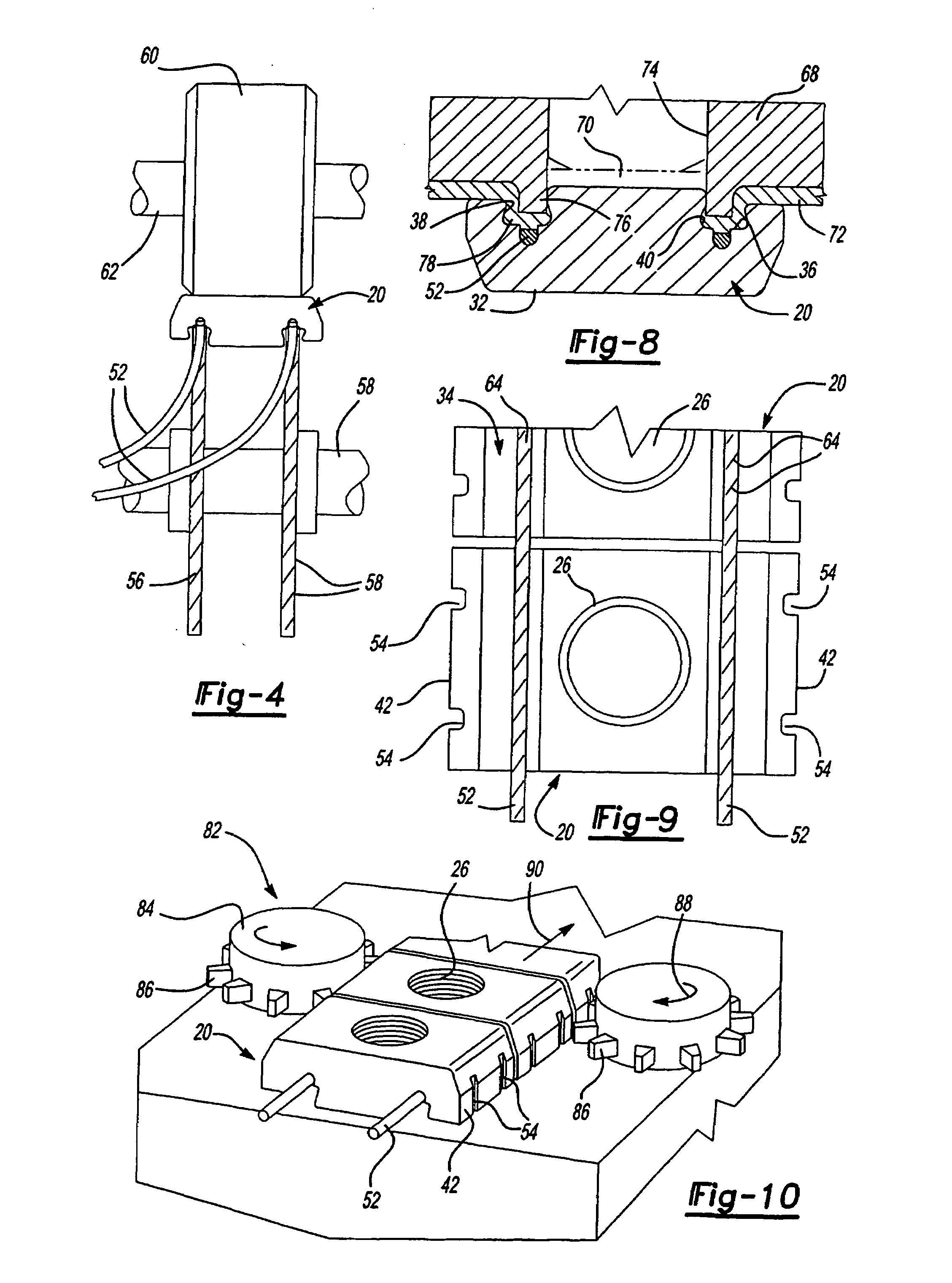
[0038]As set forth above, the present invention relates to fastener systems, particularly but not exclusively self-attaching fastener systems, including preoriented self-clinching and self-piercing and clinching nuts suitable for mass production applications, wherein the fastener is permanently installed in a metal panel. FIGS. 1 to 3 illustrate one preferred embodiment of a self-attaching fastener 20 of this invention. The self-attaching fastener 20 illustrated in FIGS. 1 to 3 may be rolled from steel bar stock as described in the above-referenced U.S. Pat. No. 3,711,931, the disclosure of which is incorporated herein by reference. Further, as described above, the self-attaching fastener illustrated in FIGS. 1 to 3 may be used either as a self-clinching fastener, wherein the panel to which it is attached includes an opening configured to receive the central pilot portion 22 or a piercing and clinching fastener, wherein the top face or piercing face 24 of the pilot portion pierces a...


PUM


Abstract

Methods of forming and feeding self-attaching fasteners are disclosed wherein the strip includes a plurality of spaced abutment surfaces, preferably notches, which may be used both during the manufacturing process and feeding of a strip of fasteners to an installation head. Where the fasteners are interconnected in a strip, by frangible wires, the wires are located in the bottom wall of the panel receiving grooves in the flange portions on opposed sides of the projecting pilot portion. A self-attaching fastener having deformable inclined lip portions which extend upwardly and toward the pilot portion from the flange portions which are deformed during installation to provide further securement for the panel when deformed in the grooves.

Description

FIELD OF THE INVENTION[0001]This invention relates to fastener systems, particularly self-attaching fastener systems, including pierce and clinch nuts having a central projecting pilot portion and flange portions on at least opposed sides of the pilot portion. More specifically, this invention relates to a method of forming self-attaching fasteners, a strip of preoriented self-attaching fasteners and methods of forming and feeding self-attaching fasteners to an installation head and fastener and panel assemblies.BACKGROUND OF THE INVENTION[0002]Self-attaching fastener systems developed by the predecessor in interest of the applicant (Multifastener Corporation) have been used for many years in mass production applications, including the automotive industry. Such fasteners generally include a central projecting pilot portion having a threaded or unthreaded bore therethrough and flange portions on opposed sides of the pilot portion. Universal™ pierce and clinch nuts commercially availa...

Claims


Application Information

Patent Timeline
Patent Type & Authority Patents(United States)
IPC IPC(8): F16B37/04B21F45/18B23P19/06F16B27/00F16B37/00F16B37/06
CPCB23P19/062F16B37/068F16B37/00F16B27/00
Inventor LADOUCER, HAROLD A.VRANA, JOHN J.
Owner PENN AUTOMOTIVE INC
Why Eureka
Try Eureka