Contamination-free edge gripping mechanism and method for loading/unloading and transferring flat objects

a flat object, contamination-free technology, applied in the direction of gripping heads, manipulators, load-engaging elements, etc., can solve the problems of unsolved contamination problems, confusion involved, add unnecessary complexity to equipment design, etc., to improve vibration-damping properties, increase the speed of gripper movement, and reduce the thickness of the transverse cross section

Inactive Publication Date: 2006-07-20
MULTIMETRIXS
View PDF6 Cites 24 Cited by
  • Summary
  • Abstract
  • Description
  • Claims
  • Application Information

AI Technical Summary

Benefits of technology

[0028] It is an object of the present invention to provide a contamination-free edge gripping mechanism for loading/unloading and transferring delicate flat objects that is capable of increasing the speed of gripper movements, has a reduced thickness in a transverse cross section, is characterized by improved vibration-damping properties, maintains soft touch in gripping under the conditions of increased speed, and reduces contamination of the objects by products of wear. It is another object to provide an edge gripper of the aforementioned type that excludes any mechanical contact of the object's face or backside with the flat surface of the gripper or with support pins. It is still another object to provide the edge gripper of the aforementioned type that simplifies loading/unloading of the wafers or wafer substrates into/from chucks of wafer processing stations. It is a further object to provide an edge gripper that makes it possible to simplify the construction of a wafer-holding chuck. Another object is to combine the aforementioned advantages with soft-touch features. It is a further object to provide a method of loading/unloading and transferring delicate flat objects with location of the gripper over the object.
[0029] Similar to a conventional edge gripper that during operation is positioned underneath an object, the griping mechanism of the present invention comprises a thin flat body having three gripping fingers that during gripping of a circular flat object such as, e.g., a semiconductor wafer, are arranged circumferentially around the object's edge. However, in contrast to the previous designs, during operation the gripping mechanism of the invention is positioned over the object. In spite of an overhead position, the gripping mechanism is contamination-free and even has much lower level of contamination than the conventional grippers positioned undernea

Problems solved by technology

This to some extent helped to reduce breakage, but did not solve the contamination problem.
However, these standards helped reduce, but did not eliminate, the confusion involved in the selection and application of robotic wafer handling.
Another compromise is the need to design semiconductor-manufacturing equipment suitable for accepting a large variety of wafer sizes.
This adds unnecessary complexity to equipment design.
Recent transfer to 300-mm wafers evolved new problems associated with much higher final cost of a single wafer (up to several thousand dollars as compared with several hundred dollars for 200 mm wafers) and thus required higher accuracy and reliability of the wafer handling equipment.
Furthermore, transition to 300 mm wafers made the use of low vacuum unsuitable for holding and handling the wafers.
Another reason is that vacuum holders are not reliable for handling wafers of heavy weight.
Thus, the conventional vacuum end effectors appeared to be unsuitable for handling expensive, heavy, and hard-to-grip wafers of 300 mm diameter.
Provision of moveable parts such as pins in the vicinity of the wafer may cause contamination of the wafer surface by the products of wear of the moveable parts.
A disadvantage of the wafer handling system of Holbrooks consists in that this apparatus does not provide control of gripping speed at different stages of the gripping cycle.
Another disadvantage of the Holbrooks system consists in that this system does not provide decrease in gripping pressure when the gripper approaches the edge of the wafer wit

Method used


Image

  • Contamination-free edge gripping mechanism and method for loading/unloading and transferring flat objects
  • Contamination-free edge gripping mechanism and method for loading/unloading and transferring flat objects
  • Contamination-free edge gripping mechanism and method for loading/unloading and transferring flat objects

Examples


Embodiment Construction

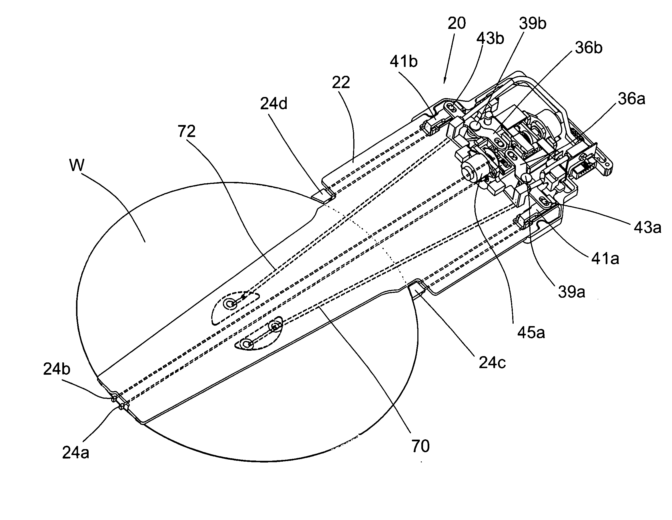
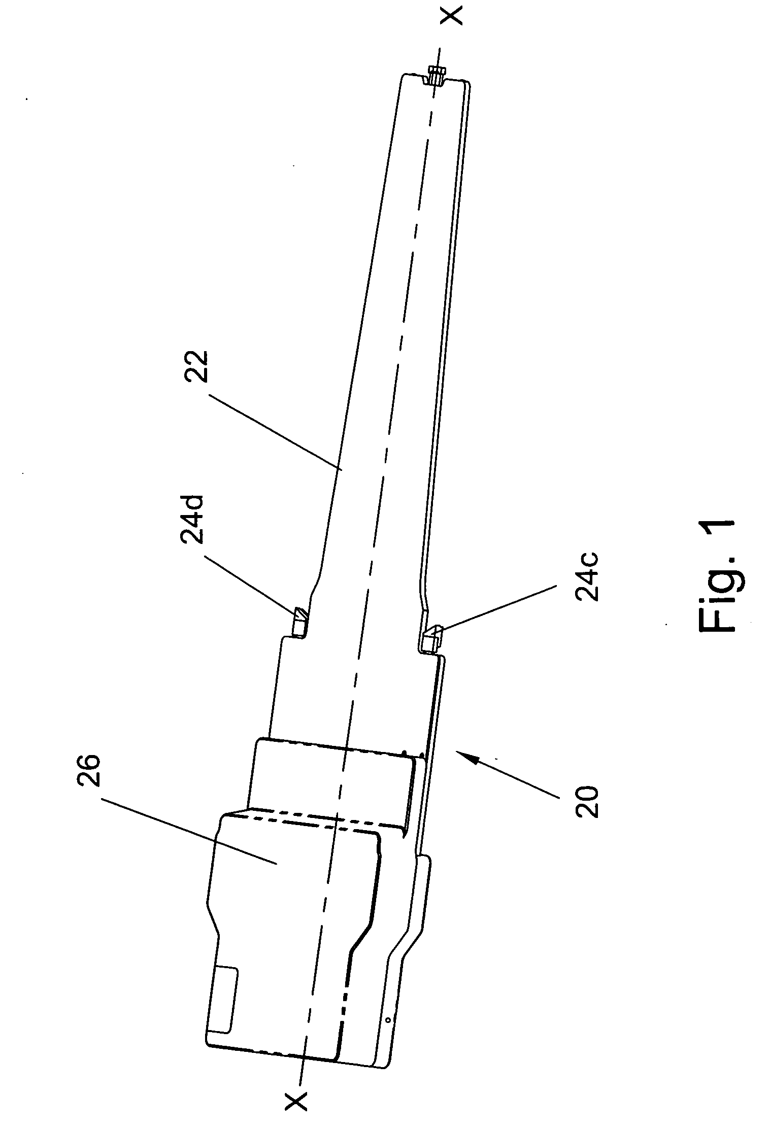
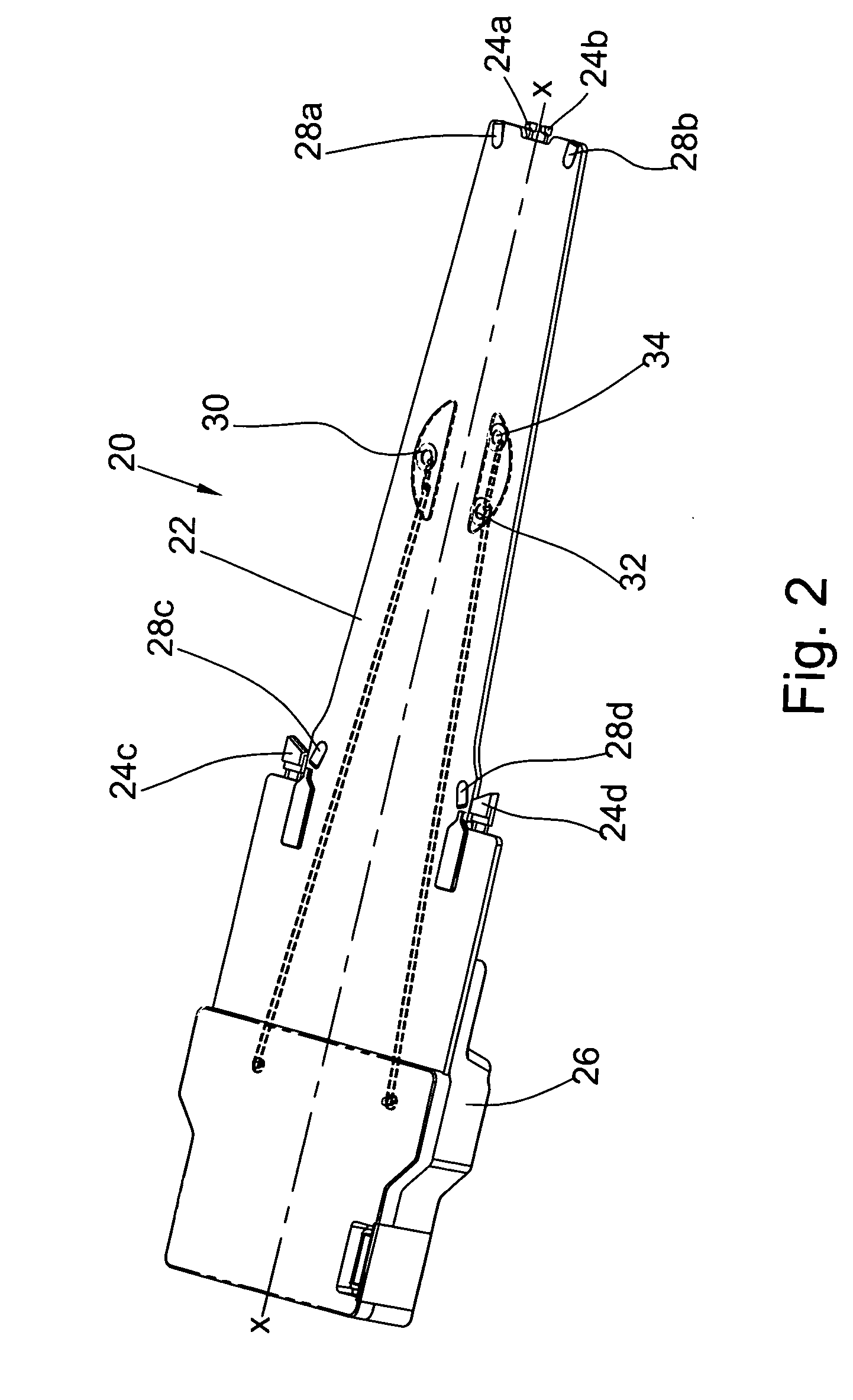
[0041] An example of an edge gripper 20 made in accordance with one embodiment of the invention is shown in FIGS. 1 and 2, wherein FIG. 1 is a three-dimensional top view of the gripper 20, and FIG. 2 is a three-dimensional bottom view of the gripper 20. It can be seen that the gripper body is comprised of a thin flat tapered plate 22 that, similar to a conventional edge gripper, supports gripping fingers located on the backside of the gripper body (FIG. 2), such as a pair of rotating distal fingers, 24a, 24b arranged essentially on the longitudinal axis X-X of the gripper 20, and a pair of proximal side fingers 24c, 24d offset from the axis X-X (FIG. 2). The gripper body 22 is a rigid hollow body made from a strong light-weight material such as amorphous aluminum for low temperature applications (not exceeding 300° C.) or titanium for high-temperature applications (exceeding 300° C.). The thickness of the gripper body 22 does no exceed 3 mm. The use of such relative soft materials i...


PUM


Abstract

The griping mechanism of the present invention comprises a thin flat body having two linearly moveable side fingers and a pair of rotating and linearly moveable distal fingers. In contrast to gripper of conventional design, the gripping mechanism of the invention is positioned over the object. In spite of an overhead position, the gripper is contamination-free since it has a completely closed design. In the vicinity of the gripping fingers, the mechanism is provided with soft edge-supporting pads having tapered surfaces for self-alignment and centering of the circular objects. The pads also eliminate surface contact between the wafer and the surface of the gripper body. The overhead position of the gripper makes it possible to simplify the construction of a wafer-holding chuck, e.g., on wafer processing stations. The gripper has auxiliary object-uplifting means in the form of vacuum suction ports or blowing nozzles that generate a vortex effect for uplifting the objects to the level required for edge gripping.

Description

CROSS-REFERENCES TO RELATED APPLICATIONS [0001] The present patent application is related to U.S. patent application Ser. No. 09 / 944,605 filed by B. Kesil, et al. on Sep. 4, 2001 and entitled “Precision Soft-Touch Gripping Mechanism for Flat Objects and to U.S. patent application Ser. No. 10 / 719,411 filed by B. Kesil et al., on Nov. 24, 2003 which is a continuation-in-part of aforementioned U.S. patent application Ser. No. 09 / 944,605, which is entitled “Soft-Touch Gripping Mechanism for Flat Objects”.FIELD OF THE INVENTION [0002] The present invention relates to the field of material handling equipment, in particular to mechanisms and methods used in semiconductor production, disk-drive manufacturing industry and the like for precision gripping, transferring, and positioning delicate, thin and highly accurate flat objects such as semiconductor wafers, hard disks, etc. More specifically, the present invention relates to an edge gripping mechanism for transferring semiconductor wafer ...

Claims


Application Information

Patent Timeline
IPC IPC(8): B25J15/08
CPCH01L21/68707
Inventor GERSHENZON, ELIKKESIL, BORIS
Owner MULTIMETRIXS
Why Eureka
Try Eureka