Two-part handle system for horticultural tray

a horticultural tray and handle technology, applied in the field of multi-cell trays, can solve the problems of slipping and falling of the handle, unable to maintain the secure engagement of the handle in the tray opening, and unable to properly insert the end portions into the tray opening in the proper position,

Inactive Publication Date: 2014-09-09
AFTEX ENTERPRISES
View PDF12 Cites 2 Cited by
  • Summary
  • Abstract
  • Description
  • Claims
  • Application Information

AI Technical Summary

Benefits of technology

[0034]The tray opening is defined by a surface with an edge. The flexible part cooperates with the edge as the connector is inserted into the tray opening to cause the flexible part to move radially inwardly to a flexed position, permitting the tray engaging section of the connector to be received in the opening. Thereafter, the flexible part returns to its extended position under the opening defining surface to prevent the connector from being dislodged from the opening.
[0044]The flexible part of the connector cooperates with the tray to prevent the free rotation of the connector relative to the tray, when the connector is received in the tray opening.

Problems solved by technology

Although such conventional handles are inexpensive to produce, they suffer from a variety of drawbacks.
They are easy to mount to the tray by flexing the end portions and inserting them into the tray openings but the handles do not remain securely engaged in the tray openings.
That is because, if the handle end portions are made to be very flexible for easy insertion into the tray openings, they tend to accidently dislodge from the tray openings when the tray is picked up by the handle, particularly when the tray is heavily weighted with soil and plants.
On the other hand, if the end portions of the handle are made less flexible, so as to more securely engage the tray, it becomes more difficult and time consuming to properly insert the end portions into the tray openings in the proper position.
The conventional handles are particularly difficult to mount to the tray at certain times during the growing cycle of the plants.
Due to high transportation costs, empty trays are transported in multi-unit stacks from the manufacturer to the location where the plants seedlings are inserted into the soil in the tray cells to grow.
Because the openings in the tray into which the handle end portions are received are located in the plane of the top surface of the tray, once the plants grow above that plane, the openings may become partially or completely obscured by the plants.
It is then often difficult for the person mounting the handles to locate the openings in order to insert the end portions of the handles.
The result is that the handle mounting process is more time consuming and the plants may be damaged during the handle mounting process.
Otherwise, the handle may dislodge when the tray is picked up.
Accordingly, the mounting procedure is labor intensive and requires substantial time to complete successfully.
As a result, once mounted, the handle is not fixed in the upright position and the handle may move to a position in which it cannot be easily grabbed.
With conventional handles, it is virtually impossible to carry more than one tray in each hand and thus an individual can carry two trays at most.
If one does try to carry more than one tray in a single hand, the trays must be held at an awkward angle and the end portions of the handle may dislodge because of the extra force applied to them.
This becomes a particularly troublesome problem at retail when a consumer wishes to purchase more than two trays.
Because the consumer can only carry two trays at a time, often the consumer will buy only two, limiting the number of trays that are sold.
However, that is often not the case with conventional handles because of the size and the position of the openings in the tray.
With conventional handles, there is no structure to keep the handle end portions centered within the tray openings.
Movement of an end portion from a position at the center of a tray opening may result in accidental detachment of the handle from the tray.

Method used


Image

  • Two-part handle system for horticultural tray
  • Two-part handle system for horticultural tray
  • Two-part handle system for horticultural tray

Examples


Embodiment Construction

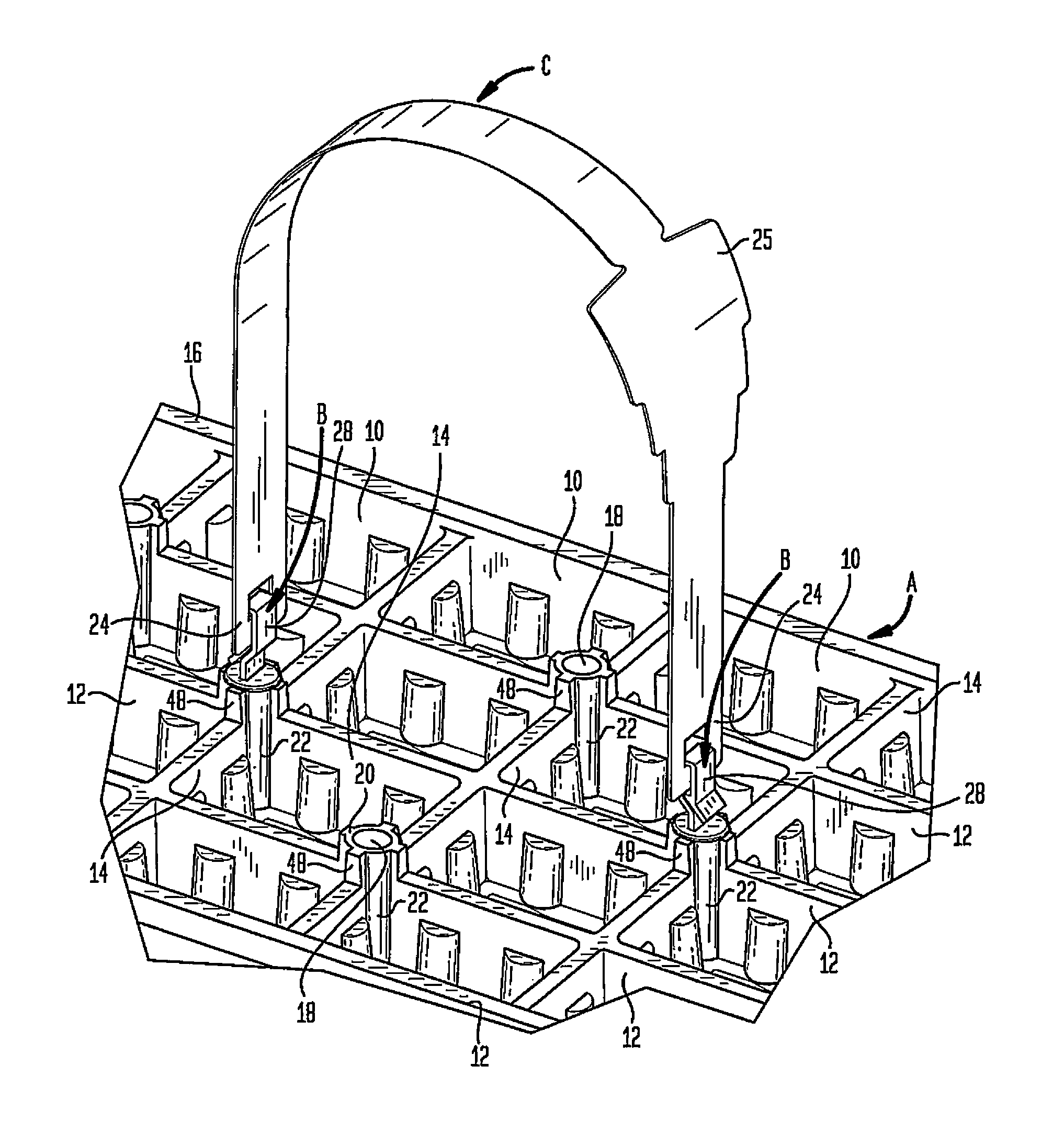
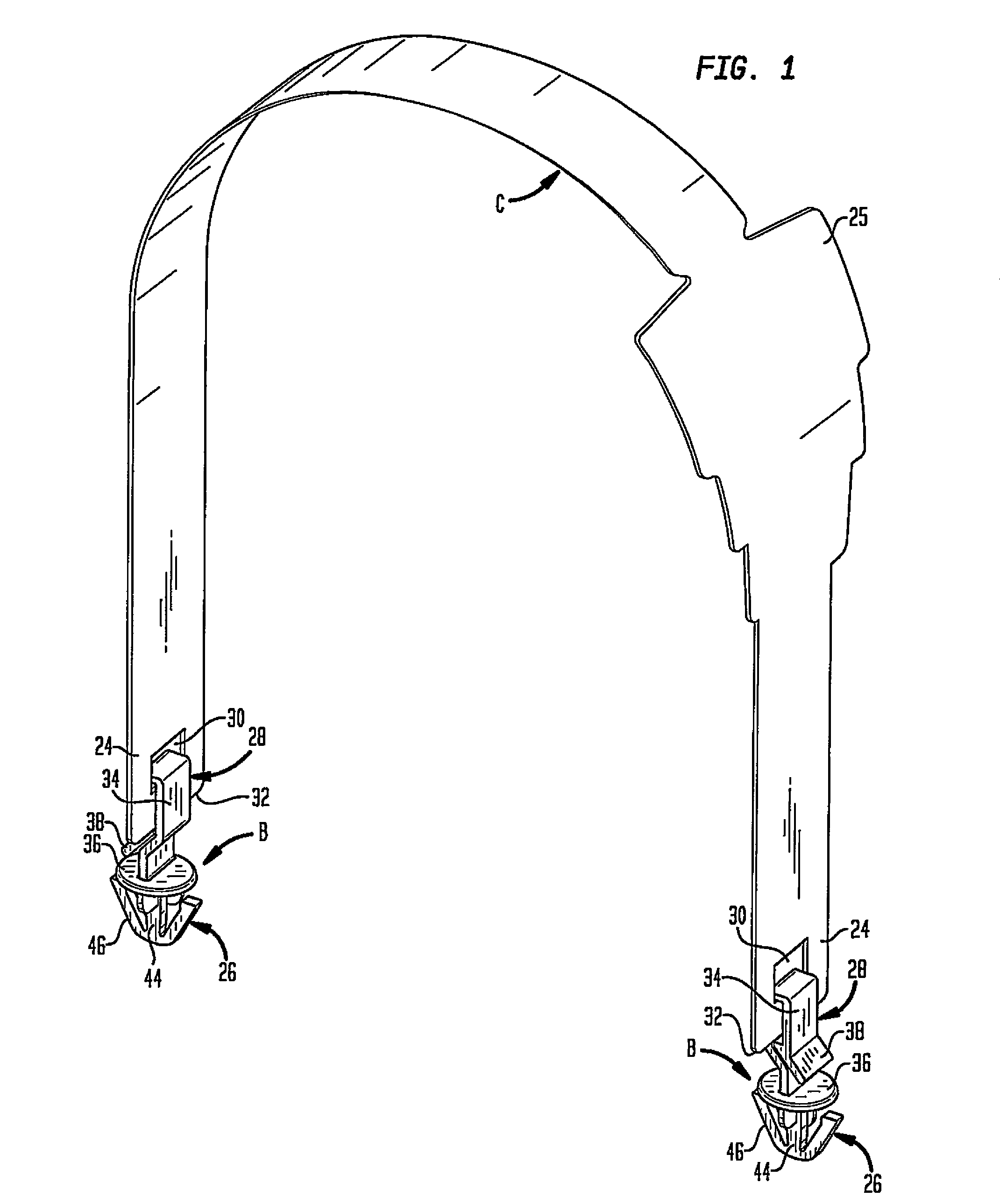
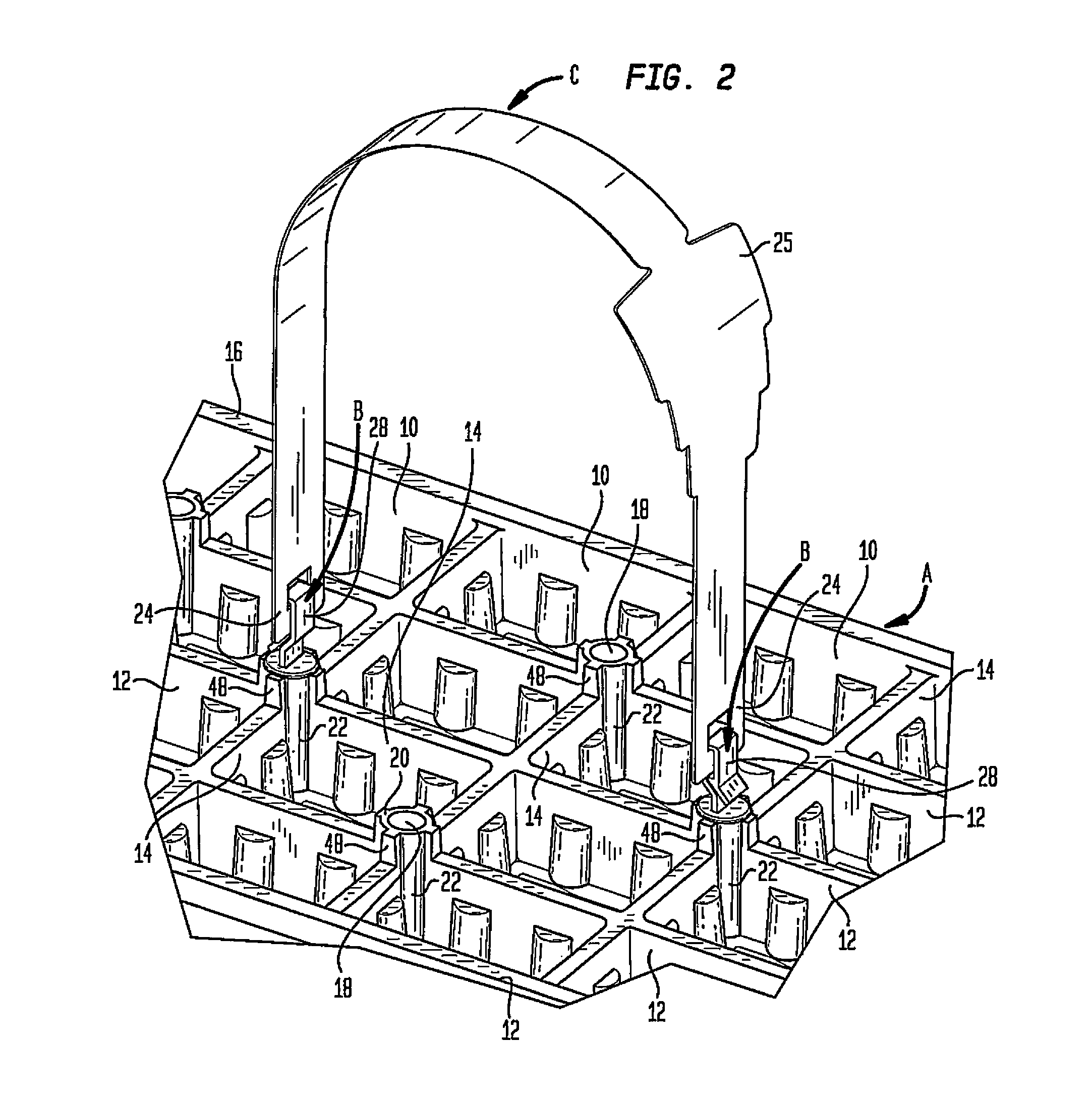
[0058]FIG. 1 illustrates the two-part handle system of the present invention. FIGS. 2 and 3 respectively illustrate the two-part handle system of the present invention before and after the two-part handle system is mounted to the horticultural tray.

[0059]As seen in FIGS. 1, 2 and 3, the horticultural tray, generally designated A, is adapted to receive the two-part handle system which consists of connectors, generally designated B, and a handle, generally designated C. Handle C is mounted to tray A by two connectors B, one at each end portion of the handle.

[0060]The tray has a plurality of cells 10. Each cell 10 is adapted to receive soil (not shown) into which one or more plant seedlings will be inserted and within which the seedlings will grow. The cells of the tray are defined by orthogonal walls 12, 14 extending between the side walls 16 of the tray.

[0061]The tray is provided with a plurality of openings 18, each adapted to receive a connector B. Each tray opening 18 is formed in...


PUM

PropertyMeasurementUnit
flexibleaaaaaaaaaa
timeaaaaaaaaaa
diameteraaaaaaaaaa

Abstract

The handle end portions are attached to the tray by separate connectors. The tray has spaced openings to receive the connectors. Each connector has an anchor-shaped section which is received in a tray opening and a section which engages a handle end portion. The anchor-shaped section has arms which flex to permit the connector to be received in the tray opening and thereafter return to their extended position to cooperate with the tray to securely attach the connector to the tray and prevent free rotation of the connector. The handle engaging section includes a hook-shaped member which is received an opening in the handle end portion.

Description

CROSS-REFERENCE TO RELATED APPLICATIONS[0001]Not ApplicableSTATEMENT REGARDING FEDERALLY SPONSORED RESEARCH OR DEVELOPMENT[0002]Not ApplicableREFERENCE TO A “SEQUENCE LISTING”, A TABLE, OR A COMPUTER PROGRAM LISTING APPENDIX SUBMITTED ON COMPACT DISC[0003]Not ApplicableBACKGROUND OF THE INVENTION[0004]1. Field of the Invention[0005]The present invention relates to multi-cell trays for packaging, transporting and displaying groups of horticultural products such as flowers, herbs and other plants, and more particularly to a handle system for such horticultural trays which utilizes separate connectors to facilitate mounting of the handle to the tray in a highly secure manner.[0006]2. Description of Prior Art Including Information Disclosed Under 37 CFR 1.97 and 1.98[0007]Multi-cell plastic trays for use in packaging, transporting and displaying groups of plants, such a flowers and herbs, are well known in the art. Because it is desirable that the trays be able to be held and carried ea...

Claims


Application Information

Patent Timeline
Patent Type & Authority Patents(United States)
IPC IPC(8): B65D25/00B65B5/06B65D25/28F16B1/00F16B21/08F16B45/00
CPCB65D25/28B65B5/068F16B1/00F16B21/086F16B45/00Y10T24/306Y10T24/307Y10T24/45921Y10T29/49947B65D25/2823Y10T24/44026Y10T24/30Y10T24/304
Inventor FRANZONE, JR., ANDREWSPERLING, JOHN
Owner AFTEX ENTERPRISES
Why Eureka
Try Eureka