
Agile decoder

a decoder and encoder technology, applied in the field of decoders, can solve the problems of inability to change firmware in real-time, multiple chipsets can prove to be very expensive, and the relative length of firmware, so as to achieve the effect of reducing the number of decoders, and increasing the flexibility of decoding process

Inactive Publication Date: 2014-09-09
GVBB HLDG R L
View PDF15 Cites 0 Cited by
  • Summary
  • Abstract
  • Description
  • Claims
  • Application Information

AI Technical Summary

Benefits of technology

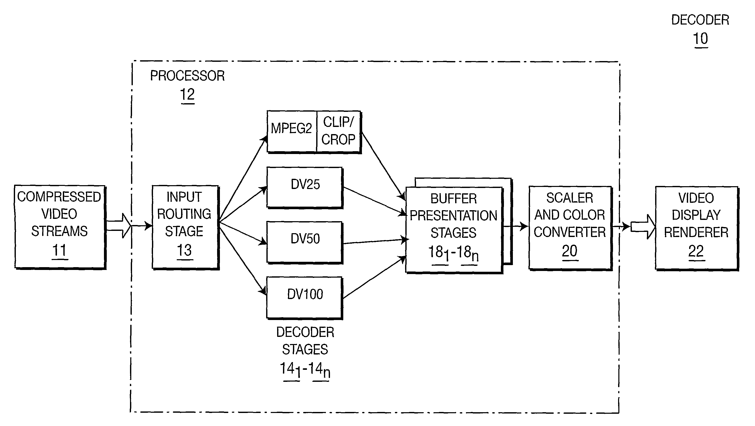
[0007]In practice, the decoder arrangement of the present principles comprises a processor programmed with software to perform the function of each of the decoder stages. Software decoders allow for a high degree of customization and afford greater flexibility and control over the decoding process. Source video material used in non-linear editors (NLEs) can come from different sources and can undergo compression in different formats, such as MPEG2, DV, JPG2K for example. The material also can have different presentation sizes, for instance, standard definition NTSC vs. high-definition 1080i. The decoder arrangement of the present principles can decode video streams regardless of their native compression format or image size by making use of decoder stages capable of decoding different formats. The decoder arrangement of the present principles can decompress frames of different formats and compose the uncompressed frames onto a common “canvas.” Further, with the availability of relatively inexpensive multiprocessor systems, the decoder arrangement of the present principles can execute on multiple parallel threads so that processing throughput can scale with the number and speed the available processors.

Problems solved by technology

With hardware decoder implementations, decoding streams of different formats usually requires a different chipset for each stream type and relatively lengthy firmware downloads.
Multiple chipsets can prove to be very costly and making firmware changes in real-time becomes impractical.

Method used


Image

  • Agile decoder
  • Agile decoder

Examples


Embodiment Construction

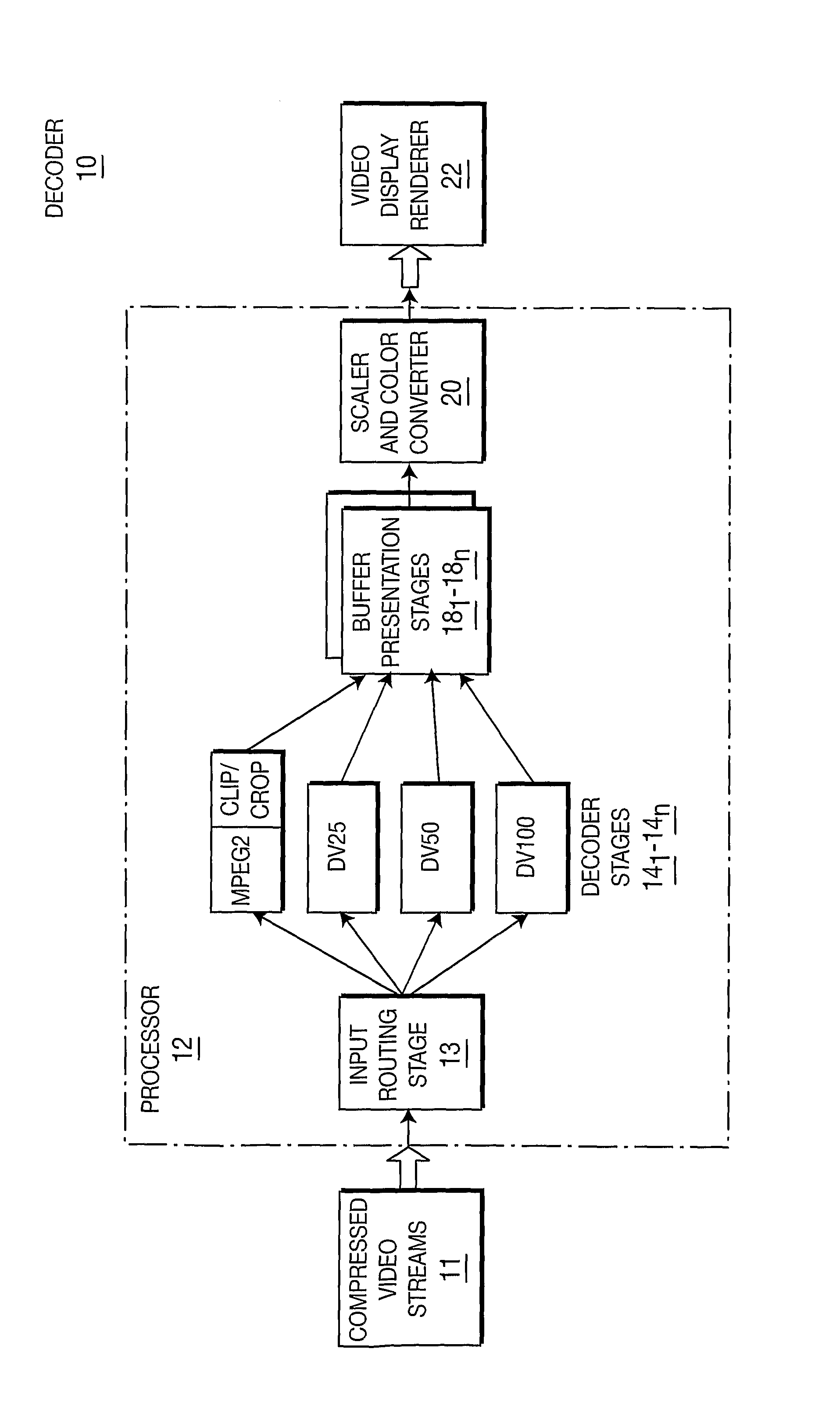
[0009]FIG. 1 depicts a block schematic drawing of a decoder arrangement 10 in accordance with a preferred embodiment of the present principles for uncompressing a plurality of compressed video streams 111-11n, where n is an integer greater than zero. In practice, one or more of the video streams 111-11n can have a different format from the others. For example, one of the streams can take the form of an MPEG 2 stream, while another stream could take the form of a DV25 or DV50 stream. The particular format of each stream remains unimportant, as long as the particular format of the stream is known a priori.

[0010]In practice the decoder 10 of the present principles comprises a programmed processor 12, such as a microprocessor, microcomputer or the like, which operates in stages as described in greater detail below. When programmed to operate as a software decoder, the processor 12 will possess an input routing stage 13 that routes the compressed video streams 111-11n to an appropriate o...


PUM


Abstract

A decoder arrangement (10) includes a processor (12) programmed to decode multiple streams (111-11n), including multiple streams of different formats. In terms of functionality, the decoder arrangement includes a routing stage (13) routes each streams to different decoder stages (141-14n), each capable of decoding a stream of a particular format to yield an uncompressed stream at its output. Each of plurality of buffer stages (161-16n) stores a successive frame of an uncompressed stream output by an associated decoder stage. An output stage scales and the frames stored by the buffer stages to a common size for input to a display device (22).

Description

CROSS-REFERENCE TO RELATED APPLICATIONS[0001]This application claims priority under 35 U.S.C. 119(e) to U.S. Provisional Patent Application Ser. No. 60 / 653,538, filed Feb. 16, 2005, the teachings of which are incorporated herein.[0002]This application claims the benefit, under 35 U.S.C. §365 of International Application PCT / US2006 / 003520, filed Feb. 1, 2006 published in accordance with PCT Article 21(2) on Aug. 24, 2006 in English.TECHNICAL FIELD[0003]This invention relates to a decoder for decoding compressed streams.BACKGROUND ART[0004]Traditionally, video decoders have been hardware-based. In other words, typical video decoders take the form of discrete, stand-alone devices dedicated for this purpose. With hardware decoder implementations, decoding streams of different formats usually requires a different chipset for each stream type and relatively lengthy firmware downloads. Multiple chipsets can prove to be very costly and making firmware changes in real-time becomes impractica...

Claims


Application Information

Patent Timeline
Patent Type & Authority Patents(United States)
IPC IPC(8): G06K9/36H03M7/34H04N7/18H03M5/00G09G5/02G06K9/46G09G5/00H04N7/12H04L12/26H04N5/907H04N7/14
CPCH04N19/42H04N19/00533H04N19/00478H04N19/12H04N19/44H04N19/00078
Inventor DELUCA, MICHAEL, ANTHONY
Owner GVBB HLDG R L
Learn More