Skylight window dormer

a dormer and skylight technology, applied in skylights/domes, building roofs, roofing, etc., can solve the problems of limited light collection, conventional flat skylights do not provide additional space in attic rooms, and conventional dormers are even more limited

Inactive Publication Date: 2014-09-23
WILDEMAN ROY C
View PDF31 Cites 3 Cited by
  • Summary
  • Abstract
  • Description
  • Claims
  • Application Information

AI Technical Summary

Benefits of technology

[0012]The two panels forming the elliptically curved skylight window dormer of the present invention are elliptically shaped with an upper panel, having an elliptical curved shaped, forming a roof or upper surface of the elliptically curved skylight window dormer and a front panel, also having an elliptical curved shaped, forming window or front surface. The panels are assembled in a framework, made of rigid material, such as metal, wood and so forth, and sealed in the framework to provide struct

Problems solved by technology

Such conventional skylights have a drawback in that the collection of light is limited by the placement of the sky light on a side or exposure of a pitched roof in relation to the placement of the sun during the day.
In addition, conventional flat skylights do not provide

Method used


Image

  • Skylight window dormer
  • Skylight window dormer
  • Skylight window dormer

Examples


example 1

[0085]

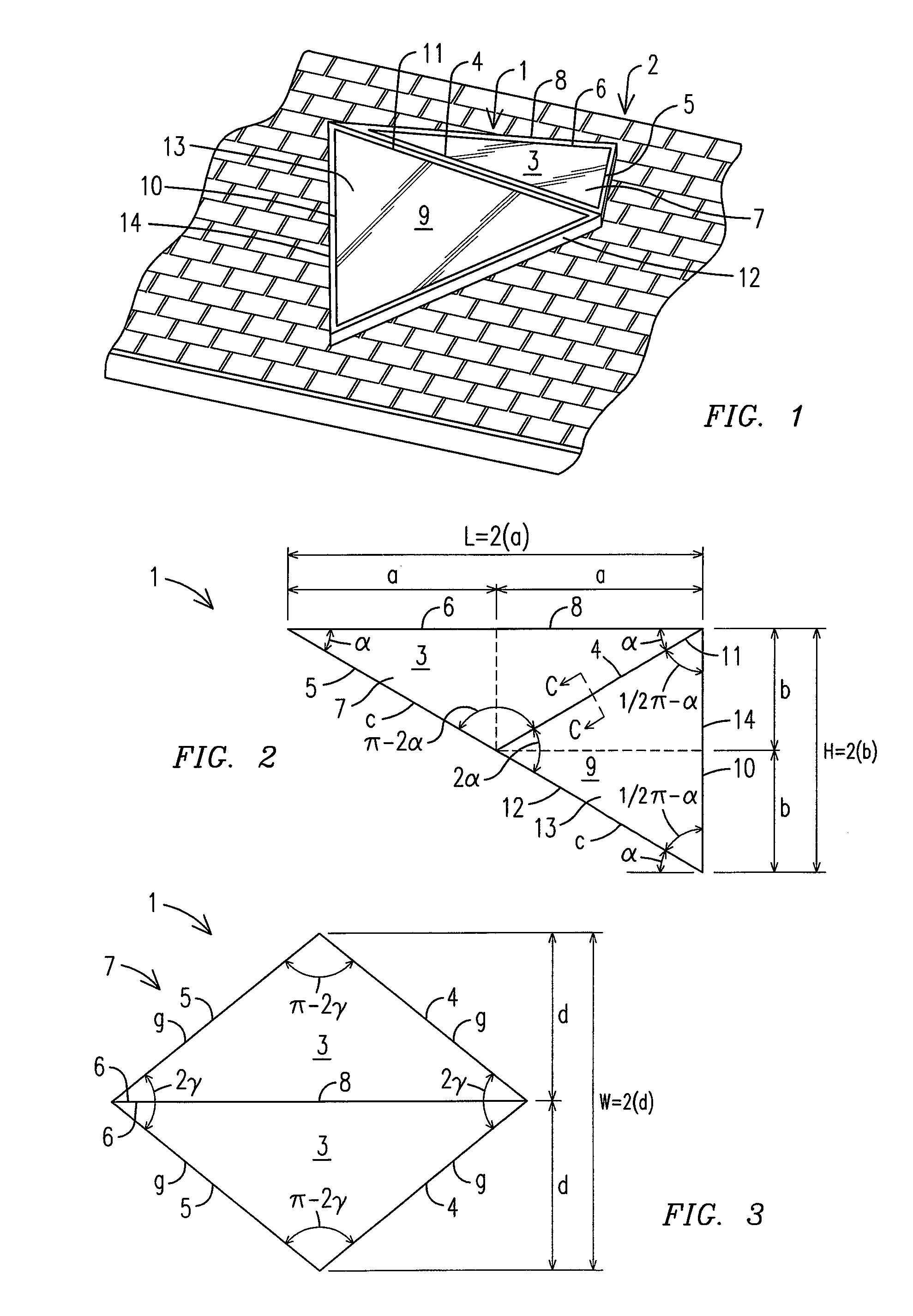
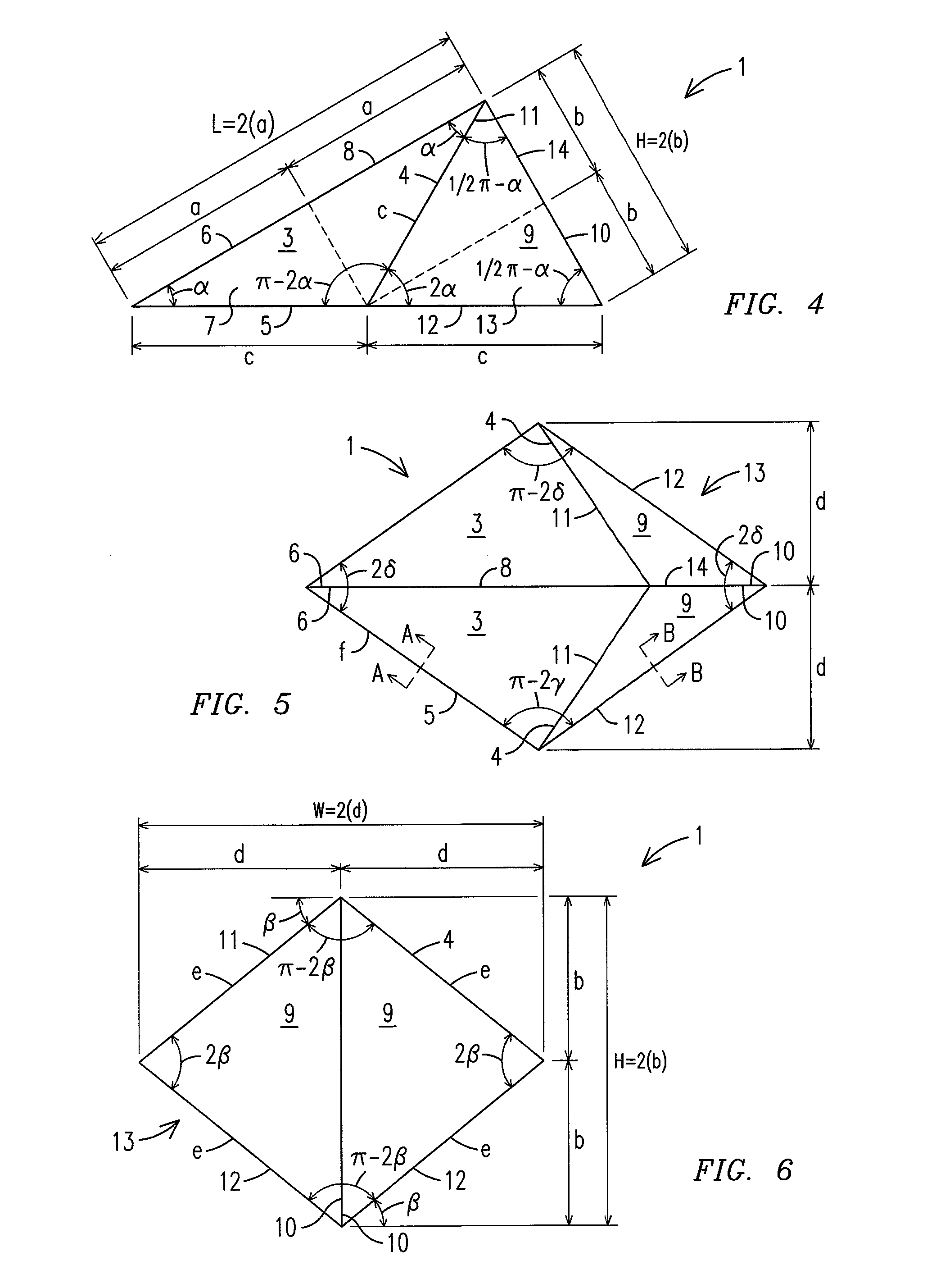
a = 6.00tan α = .5833α = 30.24b = 6.00 × .5833 = 3.50tan β = 3.50 / 6.00 = .5833β = 30.24c = 6.00(1 + .58332)1 / 2 = 6.95tanδ = 6.00 / 6.95 = .8633δ = 40.80d = 6.00sin δ = 6.00 / 9.18 = .6536δ = 40.80e = 6.00(1 + .58332)1 / 2 = 6.95tan γ = 6.00 / 6.00 = 1.000γ = 45.00f = (48.30 + 36.00)1 / 2 = 9.18tan ρ = .5833 / .6536 = .8924ρ = 41.75g = 6.00(1 + 1.0002)1 / 2 = 8.48tan φ = 1 / (.5833)(.6536) =φ = 69.132.623Host Roof Slope = 7:12tan λ1 = .5833 × .6536 = .3812λ1 = 20.87tan λ2 = .6536 / .5833 = 1.1205λ2 = 48.25

example 2

[0086]

a = 6.00tan α = .5833α = 30.24b = 6.00 × .5833 = 3.50tan β = 3.50 / 3.50 = 1.000β = 45.00c = 6.00(1 + .58332)1 / 2 = 6.95tan δ = 3.50 / 6.95 = .5036δ = 26.73d = 3.50sin δ = 3.50 / 7.78 = .4499δ = 26.73e = 3.50(1 + 1.0002)1 / 2 = 4.95tan γ = .5833γ = 30.24f = (48.30 + 12.25)1 / 2 = 7.78tan ρ = .5833 / .4499 = 1.2965ρ = 52.36g = 6.00(1 + .58352)1 / 2 = 6.95tan φ = 1 / (.5833)(.4499) =φ = 75.303.811Host Roof Slope = 7:12tan λ1 = .5833 × .4499 = .2624λ1 = 14.70tan λ2 = .4499 / .5833 = .7713λ2 = 37.64

example 3

[0087]

a = 5.00tan α = .5833α = 30.24b = 5.00 × .5833 = 2.92tan β = 2.92 / 4.00 = .7300β = 36.13c = 5.00(1 + .58332)1 / 2 = 5.79tan δ = 4.00 / 5.79 = .6908δ = 34.64d = 4.00sin δ = 4.00 / 7.04 = .5682δ = 34.64e = 4.00(1 + .72922)1 / 2 = 4.95tan γ = 4.00 / 5.00 = .8000γ = 38.66f = (33.52 + 16.00)1 / 2 = 7.04tan ρ = .5833 / .5682 = 1.0266ρ = 45.75g = 5.00(1 + .80002)1 / 2 = 6.41tan φ = 1 / .5833 × .5682 =φ = 71.663.017Host Roof Slope = 7:12tan λ1 = .5833 × .5682 = .3314λ1 = 18.34tan λ2 = .5682 / .5833 = .9741λ2 = 44.25

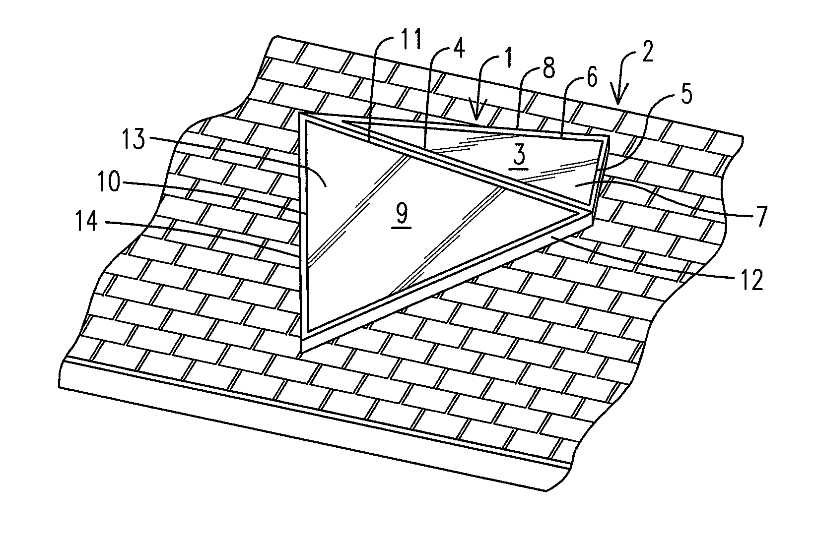
[0088]Components or preferably insulated glass panels or equivalent plastic panels configured to suit the particular geometry discussed above with all edges protected and sealed by channels which are then bonded to the panels. All connectors, as illustrated in FIGS. 13-15, may be custom configured and fabricated to attach panels to one another with a weather tight seal and trim. Four sills interconnect to form a base which is slightly smaller than a rough opening cut into a host roof to install...


PUM


Abstract

A skylight window dormer for installation on a pitched roof or sloped surface. The skylight window dormer is constructed form a plurality of triangular shaped or elliptically curved panels joined to form a dormer type structure that provides panoramic viewing and additional headroom in tightly enclosed interior spaces. The skylight window dormer is installed using a similar method as conventional skylights and is, thus, combining the efficiency of installing a conventional skylight with the benefits of additional space provided by a conventional dormer.

Description

CROSS-REFERENCE TO RELATED APPLICATIONS[0001]This application claims priority to application No. 61 / 812,044 filed on Apr. 15, 2013, which is currently pending. The patent application identified above is incorporated herein by reference in its entirety to provide continuity of disclosure.FIELD OF THE INVENTION[0002]This application relates to a skylight window having a substantially trapezoidal or ellipsoid shape to form a dormer when installed on a conventional pitched roof.BACKGROUND OF THE INVENTION[0003]Skylight windows are widely used in day lighting design in residential and commercial buildings to provide natural light through a roof of a structure. Conventional skylights normally have a perimeter frame that is rectangular with one or more pane of glass mounted within the frame and lay parallel to a pitched roof. Such conventional skylights have a drawback in that the collection of light is limited by the placement of the sky light on a side or exposure of a pitched roof in re...

Claims


Application Information

Patent Timeline
IPC IPC(8): E04B7/18E04D13/03
CPCE04D13/032
Inventor WILDEMAN, ROY, C.
Owner WILDEMAN ROY C
Why Eureka
Try Eureka