
Multi-seal knife gate valve

a gate valve and multi-seal technology, applied in the field of knife gate valves, can solve the problems of poor sealing capability, frequent leakage, maintenance cost, etc., and achieve the effects of reducing maintenance costs, improving durability and sealing capability, and reducing frequent repairs

Inactive Publication Date: 2014-09-23
HIFLY VALVE
View PDF16 Cites 8 Cited by
  • Summary
  • Abstract
  • Description
  • Claims
  • Application Information

AI Technical Summary

Benefits of technology

The present invention provides a multi-seal-type knife gate valve with good sealing capability and excellent durability. This valve retains the strengths of both metal-seat and rubber-seat valves, reducing frequent repairs and preventing shutdowns and production delays due to interruptions in valve operation. In addition, this valve prevents the intrusion of foreign matters into a product, improving the quality of the product and reducing product defectiveness. The advantages of this valve include being cost-effective and adaptable for use in various pipes.

Problems solved by technology

However, while metal seat type knife gate valves are usually used in locations that require durability, the valves have poor sealing capability so that leakage often occurs.
In the meantime, while the rubber seat type knife gate valves are used in a pipe that requires high sealing capability, the valves have poor durability to cause the problems of maintenance to occur.
However, since the metal seat type valves have excellent durability but poor sealing capability because their metal-to-metal contact structures make it difficult to maintain complete airtightness, the problems are that the valves cannot be used in pipes requiring high sealing capability.
Further, while the rubber seat type knife gate valves are used in pipes requiring high sealing capability, the valves have poor durability so that there are the problems of maintenance.
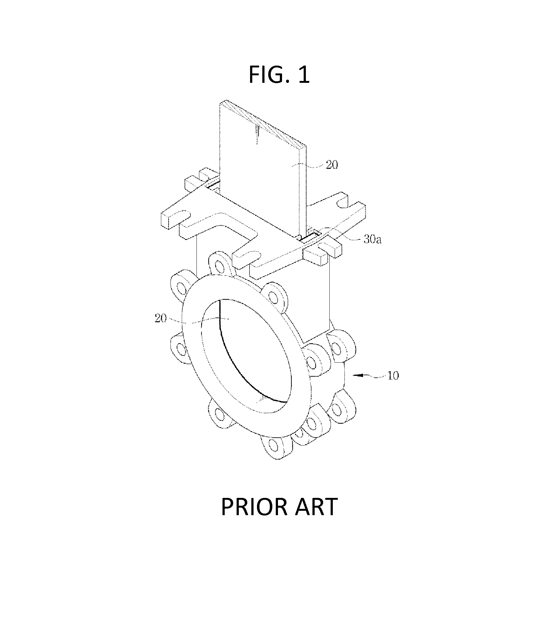
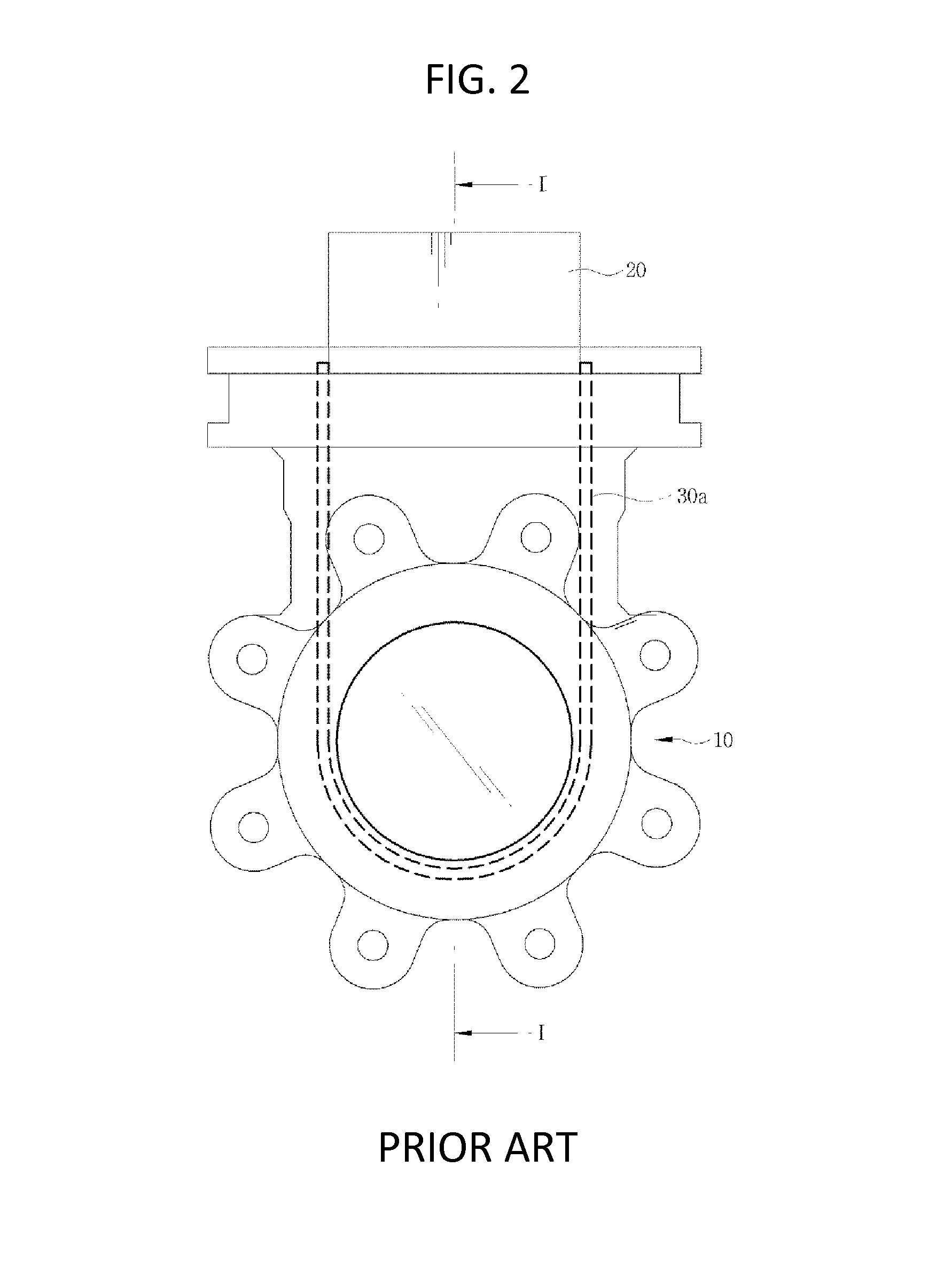
While this structure can perform complete sealing, there are drawbacks of poor durability due to severe friction because when the valve is opened and closed, the rubber seat 30a comes into simultaneous contact with opposite sides of the valve disk 20.
In addition, since the rubber seat 30a extends up to the upper portion of the inside of the valve body 10, there are the problems of leakage occurring at the upper portion of the valve.
To this end, the rubber seat 30b is fabricated into a special form by inserting a metallic support into the rubber seat, which makes it costly and difficult to fabricate.
Further, since the rubber seat 30b comes into contact with the opposite surfaces of the disk 20, the problem of poor durability arises because of severe friction occurring when the valve is opened and closed.
Further, because of the severe friction, the valve needs a great amount of actuation torque and therefore a huge driver for the actuation of the valve, problematically increasing the cost.

Method used


Image

  • Multi-seal knife gate valve
  • Multi-seal knife gate valve
  • Multi-seal knife gate valve

Examples


Embodiment Construction

[0033]Hereinbelow, preferred embodiments of the present invention will be described in detail with reference to FIGS. 6 to 11.

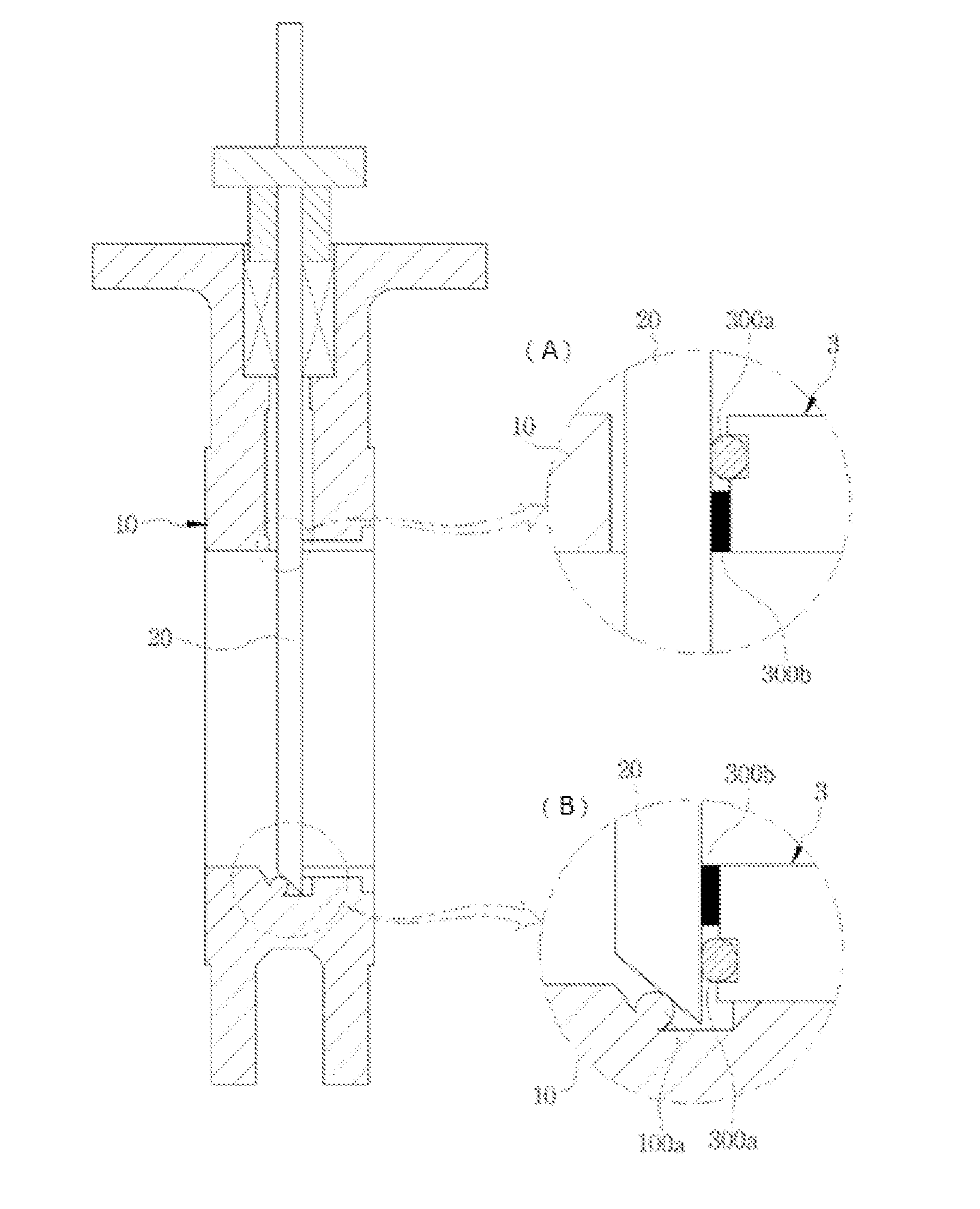
[0034]FIG. 6 is a perspective view of a knife gate valve according to an embodiment of the present invention, FIG. 7 is a cross-sectional view taken along line III-III of FIG. 6, showing the open state of a passage of a pipe before a disk is not moved down, FIG. 8 is a cross-sectional view taken along line III-III of FIG. 6, showing the closed state of the passage of the pipe before a disk has been moved down, and FIG. 9 is a perspective view of a seat ring of FIG. 6.

[0035]Referring to these drawings, the knife gate valve of the embodiment of the invention includes a valve body 10 to be coupled with a pipe (not shown), a disk 20 inserted into the valve body 10 to move vertically, and a valve seat pressed against the disk 20 so as to maintain a tight seal, wherein the valve seat is pressed against the disk 20 and has at least one rubber seat 300a and one metal...


PUM


Abstract

A multi-seal knife gate valve includes: a valve body coupled to a pipe; a disk inserted into the valve body to move vertically; and a valve seat pressed against the disk so as to maintain a tight seal, wherein the disk installed in the valve body moves vertically to open or close a passage through which fluid flows, and the valve seat is pressed against the disk and includes at least one metal seat and one rubber seat to maintain a seal.

Description

CROSS REFERENCE TO RELATED APPLICATIONS AND CLAIM OF PRIORITY[0001]This patent application is a National Phase application under 35 U.S.C. §371 of International Application No. PCT / KR2011 / 001287, filed on Feb. 24, 2011, entitled MULTI-SEAL KNIFE GATE VALVE, which claims priority to Korean Patent Application number 10-2010-0018077, filed on Feb. 26, 2010, entire contents of which are incorporated herein by reference.BACKGROUND[0002]1. Technical Field[0003]The present invention relates, in general, to a knife gate valve and, more particularly, to a multi-seal knife gate valve having improved durability and sealing capability.[0004]2. Description of the Related Art[0005]Generally, tubing systems requiring flow control use valves. Such valves are usually equipped with knife valves in order to control high viscosity fluid and the powders and solid granules to be carried. That is, such fluids impede the opening and shutting of a valve because of their clogging, friction, etc. and so a sea...

Claims


Application Information

Patent Timeline
Patent Type & Authority Patents(United States)
IPC IPC(8): F16K3/00F16K3/02
CPCF16K3/0281F16K3/0227
Inventor CHOO, YEON CHILBAEK, JAE HUN
Owner HIFLY VALVE
Learn More