Wind turbine with compensated motor torque

a wind turbine and torque technology, applied in the direction of motors, engine control, passive/reactive control, etc., can solve the problems of power peaks, unfavorable conditions for both the turbine itself and the stability, and stress that affects both the wear and tear of the turbine and the quantity and quality of energy generated, so as to minimize the shadow effect of the tower, the effect of great running stability and stable motion

Active Publication Date: 2014-09-23
TEMPERO 2000
View PDF6 Cites 5 Cited by
  • Summary
  • Abstract
  • Description
  • Claims
  • Application Information

AI Technical Summary

Benefits of technology

[0002]More particularly, the object of the invention focuses on a motor torque wind turbine which is compensated thanks to incorporating an inertial pendulum, so that its structural innovative design makes it able to capture the wind energy with less effort than traditional machines, providing more uniform and quality energy by incorporating passive mechanical systems that compensate for, accumulate and restore the power peaks and valleys caused by the wind gusts as well as instant charge variations in isolated parts of the electrical grid.
[0012]On the other hand, as it is a less overloaded structure, the turbine of the invention is also appropriate to replace old turbines, allowing making use of the tower, shoe and electrical infrastructure by increasing the areas swept by the rotor and get more equivalent hours in the same location.

Problems solved by technology

However, its lack of continuity, particularly its lack of uniformity regarding intensity and direction, cause unfavorable conditions for both the turbines itself and for the stability of the electrical system to which they connect, whose main feature must be providing continuity in the supply and tension and frequency consistency.
Thus, as the wind occurs most of the time as short duration gusts, these, by intercepting the wind turbine rotor, produce stress that affect both the wearing of the turbine and the quantity and quality of energy generated.
The rigidity, with which any variation of the torque is transmitted to the power train components up to the generator, causes power peaks that tend to destabilize the network and strain the turbine components.

Method used


Image

  • Wind turbine with compensated motor torque
  • Wind turbine with compensated motor torque
  • Wind turbine with compensated motor torque

Examples


Embodiment Construction

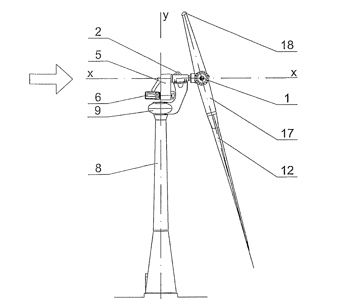
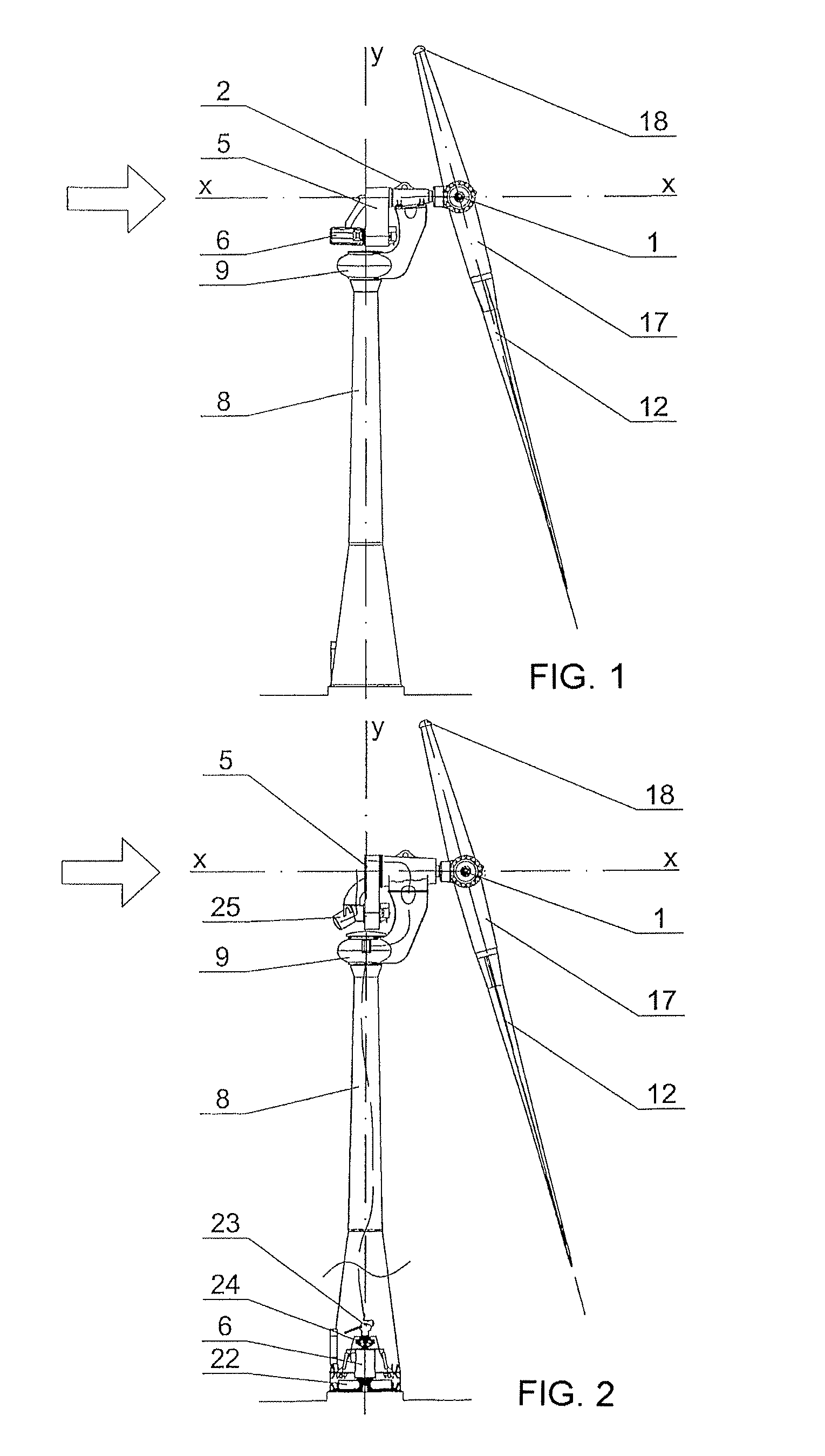
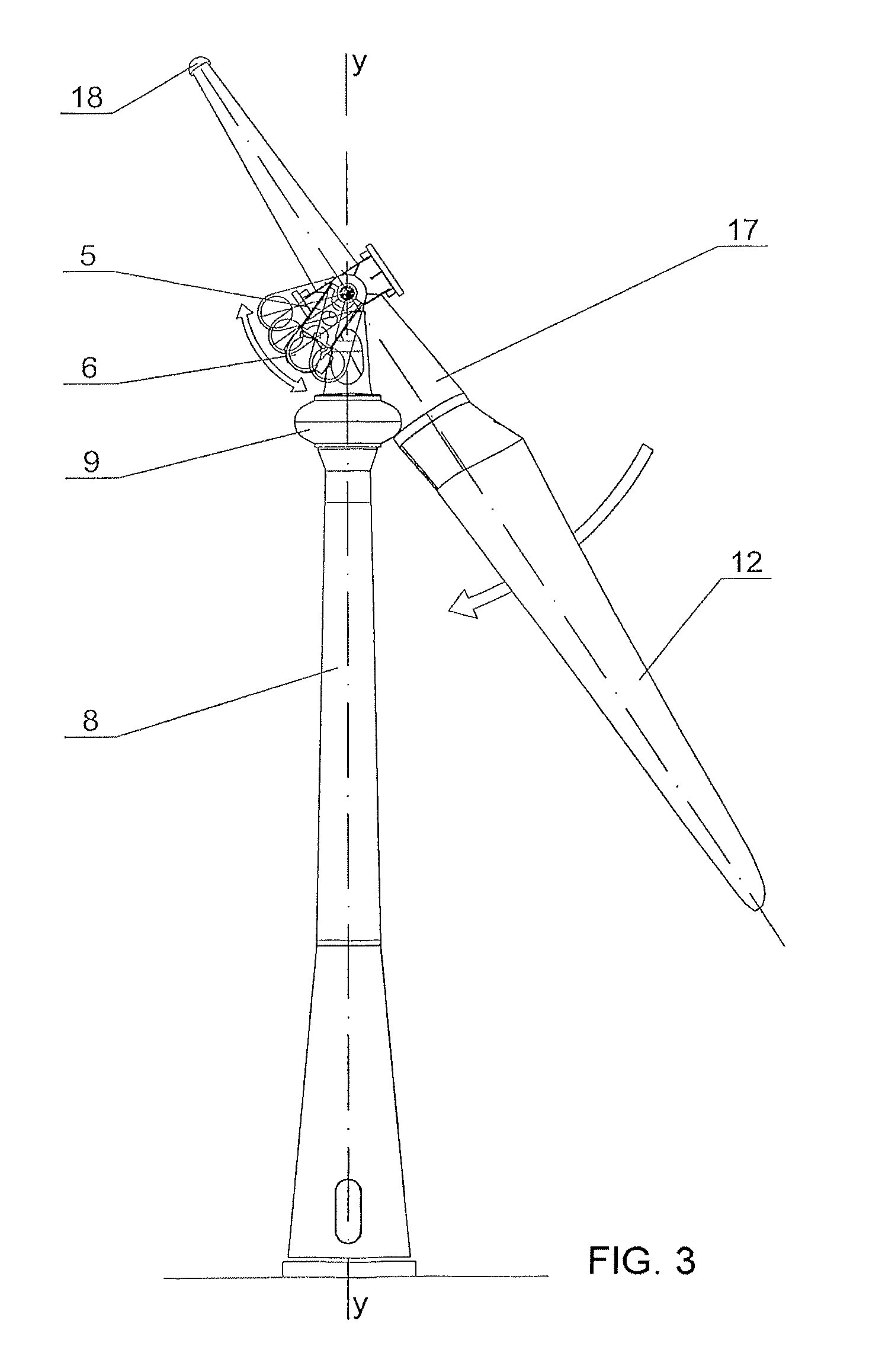
[0080]In view of the aforementioned figures, and according to the numeration adopted, an example of a preferred embodiment of the invention is shown as well as an alternative variant thereof, which comprises the parts and elements that are detailed and described below, having used the following numerical references to designate them in the figures:[0081]1. rotor[0082]2. spindle[0083]3. low speed shaft[0084]4. first bearing (pendulum set)[0085]5. multiplier[0086]6. generator[0087]7. gear bearing[0088]8. tower[0089]9. nacelle[0090]10. elastomers[0091]11. flywheel[0092]12. blade[0093]13. brake disc[0094]14. gear motor-brake[0095]15. crank arm[0096]16. fork[0097]17. hub[0098]18. counterweight[0099]19. joint[0100]20. worm screw[0101]21. mobile ring[0102]22. second flywheel[0103]23. oil hydraulic servomotor[0104]24. hydraulic coupler[0105]25. oil hydraulic central[0106]26. rotating connector[0107]27. pump[0108]28. pendulum set[0109]29. high speed shaft

[0110]Thus, as shown in said figures,...


PUM


Abstract

COMPENSATED MOTOR TORQUE WIND TURBINE, constituted by a single blade (12) rotor (1) attached to a low speed shaft (3) with spindle (2) sustained in a nacelle (9), on gear bearing (7), at the end of the tower (8), being the power train elements: multiplier (5), generator (6) and brake (13) suspended from the nacelle (9) through a first bearing (4) aligned with the low speed shaft (3), forming a pendulum set (28) that allows them to rotate, compensating in its angular motion the rotor (1) torque, said pendulum set (28) accumulates potential energy when rising in its angular motion and releases it when the gust stops by descending and turning in the opposite direction of the rotation of the turbine's rotor (1) restituting turns to the generator's (6) rotor, being this effect a power regulator.

Description

OBJECT OF THE INVENTION[0001]The invention, as expressed in the title of this specification, refers to a compensated motor torque wind turbine.[0002]More particularly, the object of the invention focuses on a motor torque wind turbine which is compensated thanks to incorporating an inertial pendulum, so that its structural innovative design makes it able to capture the wind energy with less effort than traditional machines, providing more uniform and quality energy by incorporating passive mechanical systems that compensate for, accumulate and restore the power peaks and valleys caused by the wind gusts as well as instant charge variations in isolated parts of the electrical grid.[0003]This makes it a more compatible turbine with the electrical grid, able to work while connected to weak grids, as it is a more tolerant machine, causing less disruption on the grid.[0004]Also, it is advantageously suitable to work in parallel with other energy sources when satisfying the energy demands...

Claims


Application Information

Patent Timeline
Patent Type & Authority Patents(United States)
IPC IPC(8): F03D11/02F03D1/06F03D7/02
CPCF03D1/0608F03D7/02F03D11/02Y02E10/723Y02E10/721F05B2270/1014Y02E10/726F05B2270/508F05B2270/1095Y02E10/722F05B2270/402F05B2260/421F03D15/00F03D15/10F03D80/70Y02E10/72
Inventor ROMEO, MANUEL, LAHUERTA
Owner TEMPERO 2000
Why Eureka
Try Eureka