Safety valve and method of use

a safety valve and valve body technology, applied in the field of safety valves, can solve problems such as interference with wellbore completion operations, failure of combination actuators described above, and failure to provide a visual indication whether the valve has been actuated

Active Publication Date: 2014-10-07
SAFOCO
View PDF36 Cites 10 Cited by
  • Summary
  • Abstract
  • Description
  • Claims
  • Application Information

AI Technical Summary

Problems solved by technology

Inadvertent loss of pneumatic or hydraulic pressure to the automatic actuator closes the gate valve which can interrupt production and interfere with wellbore completion operations occurring through the valve.
The combination actuators described above, however, fail to provide a visual indication whether the valve has been actuated using the mechanical override, the automatic actuation, or both.
The lack of this communication can be detrimental in various situations.
Since the mechanical override may also override the fail-safe closed mechanism, the operator is thus under the mistaken belief that the valve is operating in a safe mode.
Only a few turns of the handwheel can offset the valve gate, and yet the appearance of the handwheel shaft extending from the actuator cannot communicate this slight offset.
Thus when automatic operation occurs, the valve cannot be situated in a fully open or fully closed position, potentially causing leakage in the valve and un-even wear of the valve's seat and / or seals of the gate or body by fluid flow through the slightly offset valve.

Method used


Image

  • Safety valve and method of use
  • Safety valve and method of use
  • Safety valve and method of use

Examples


Embodiment Construction

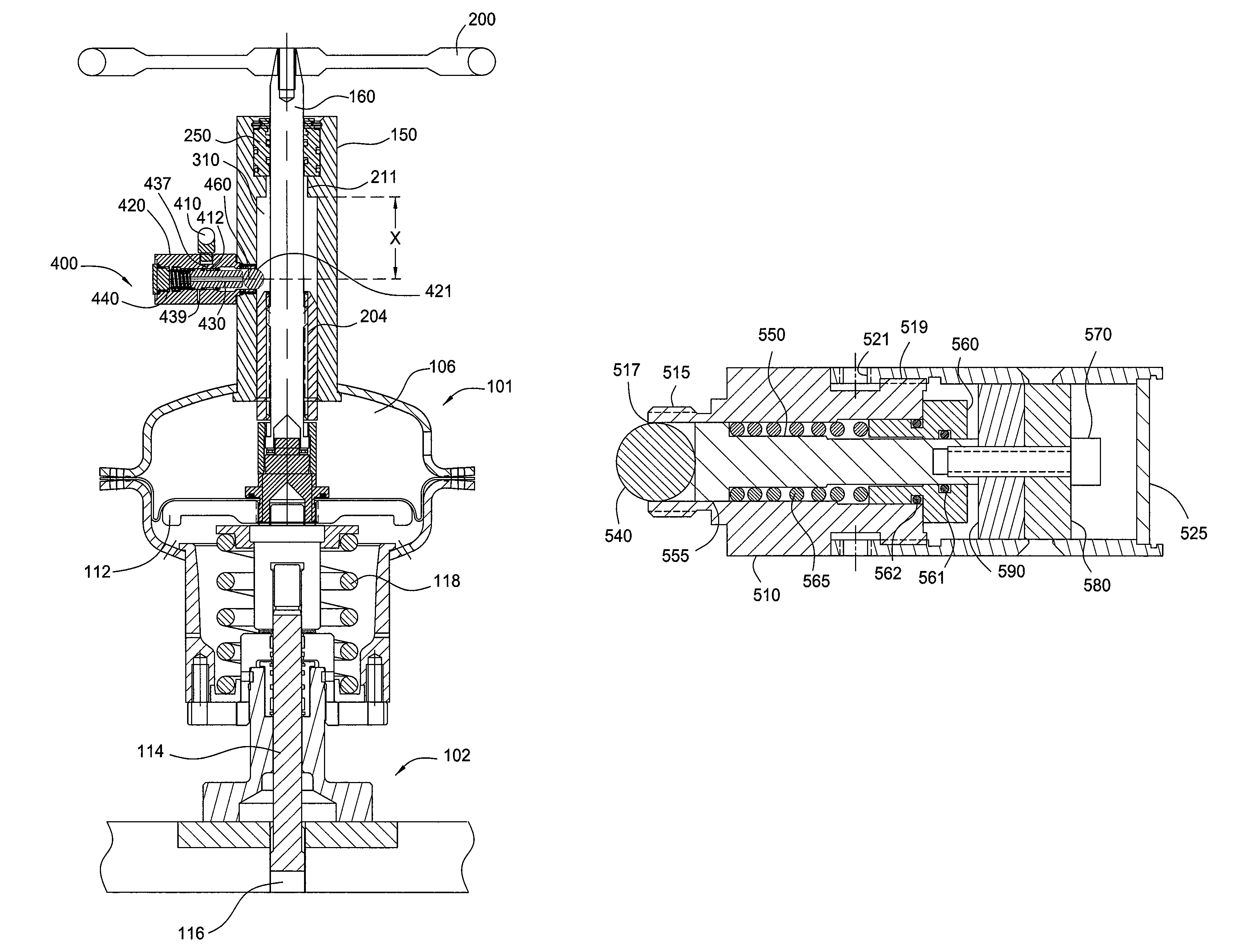
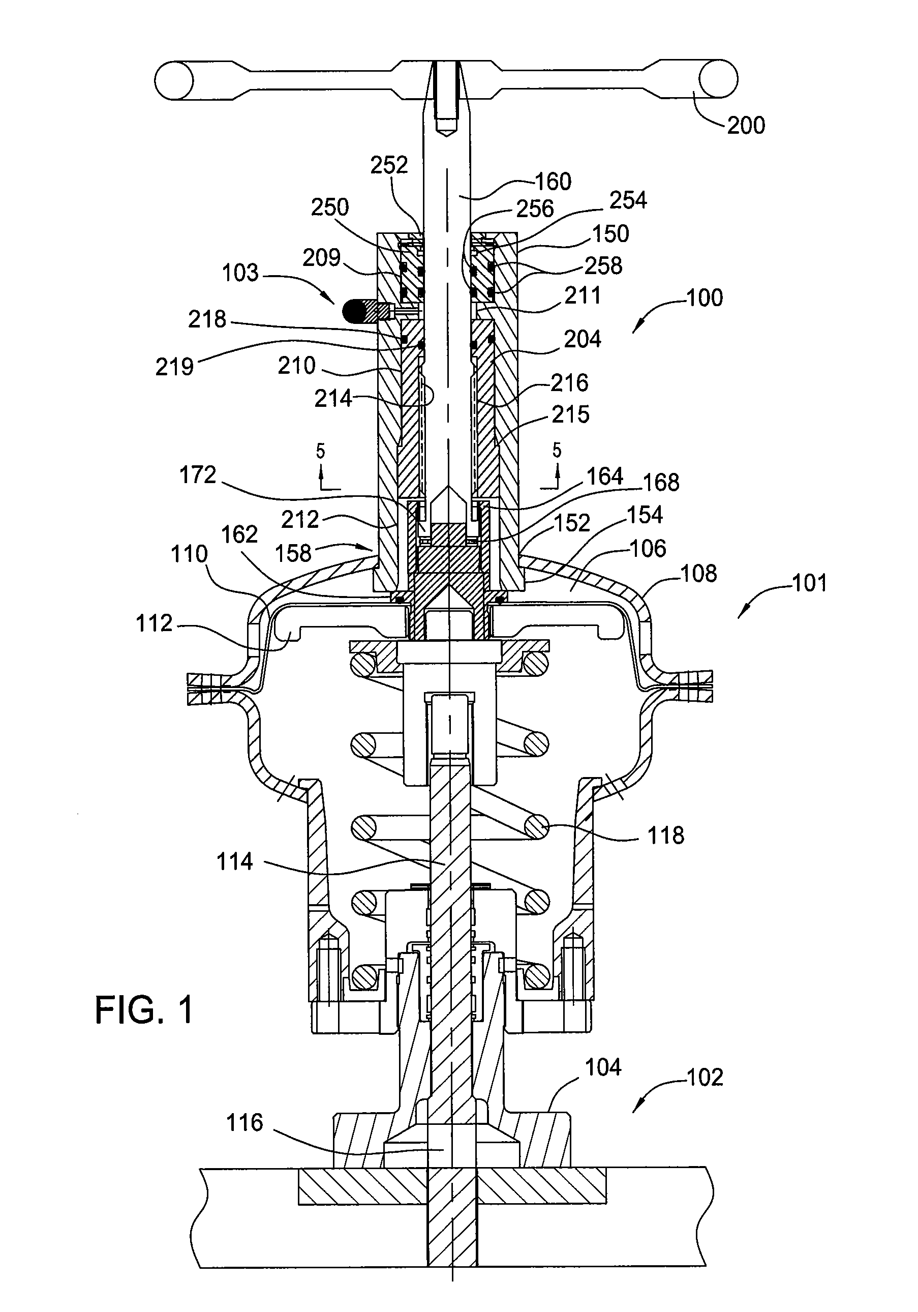
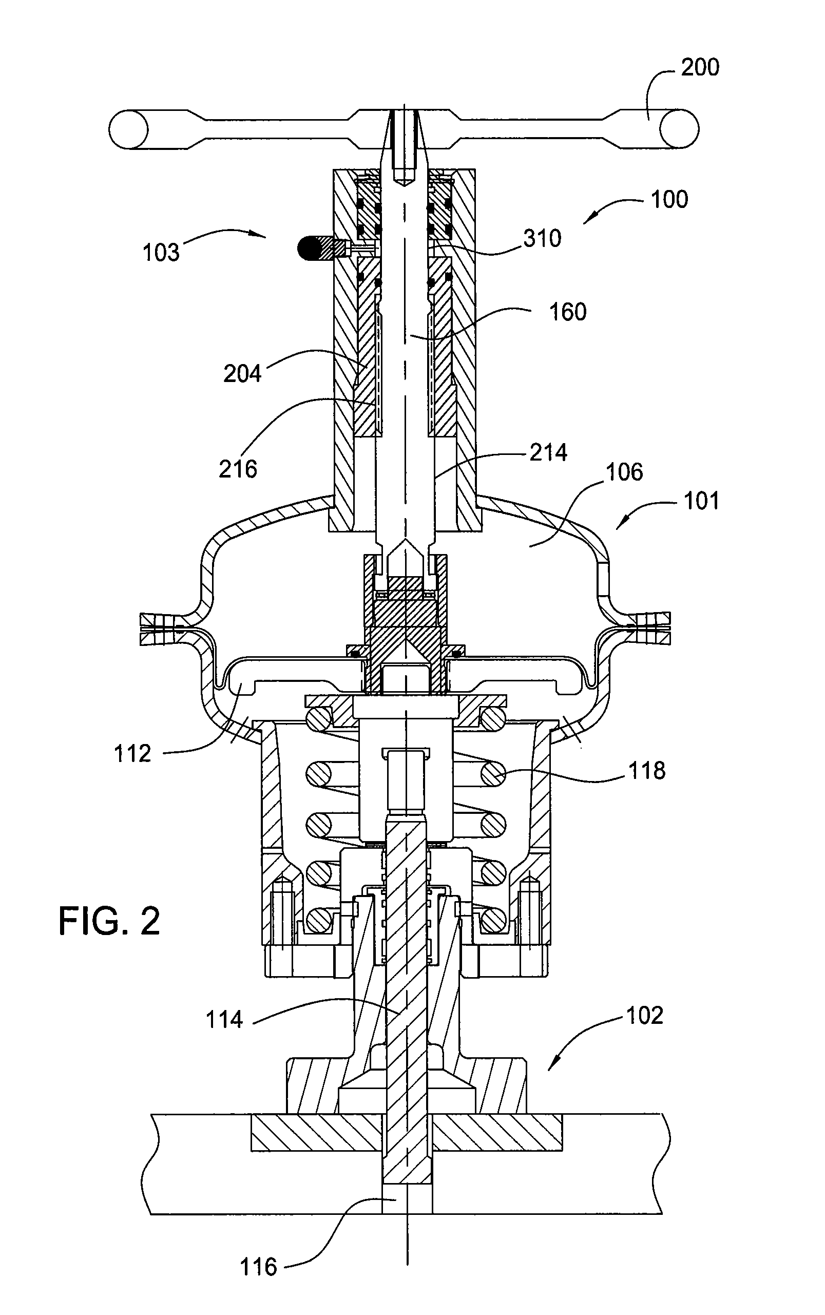
[0029]FIG. 1 is a sectional view of a mechanical override 100, an actuator 101, a gate valve 102, and a safe mode indicator 103. The actuator 101 couples to a valve body 104 of the gate valve 102. A bonnet assembly can provide an interface between the gate valve 102 and the actuator 101. During an automatic operation of the gate valve 102, hydraulic or pneumatic pressure enters a chamber 106 of the actuator 101 defined by a cover 108 of the actuator 101 and a diaphragm 110 positioned over an operator member 112. The operator member 112 moves in response to the hydraulic or pneumatic pressure within the chamber 106 and against a biasing force supplied by a spring 118. A valve stem 114 coupled to a sliding gate 116 of the gate valve 102 moves in response to the movement of the operator member 112. In this manner, the automatic operation of the actuator 101 moves the sliding gate 116 of the gate valve 102 between a closed position shown in FIG. 1 and an open position as shown in FIG. 3...


PUM


Abstract

Embodiments of a method of operating a safety valve and a safety valve system are provided. The valve system includes a valve, an actuator, a mechanical override, and an indicator. The actuator includes a fail-safe mechanism and the indicator is configured to indicate whether the fail-safe mechanism is operable during use of at least one of the actuator and the mechanical override. In one embodiment, a method of operating the safety valve includes actuating the valve into an open position and sending a signal to indicate that the fail-safe mechanism is operable to move the valve to the closed position, while the valve is in the open position.

Description

CROSS-REFERENCE TO RELATED APPLICATIONS[0001]This application is a continuation-in-part of U.S. patent application Ser. No. 13 / 073,609, filed Mar. 28, 2011, which claims benefit of U.S. Provisional Patent Application Ser. No. 61 / 319,697, filed Mar. 31, 2010, and U.S. Provisional Patent Application Ser. No. 61 / 356,506, filed Jun. 18, 2010, which applications are herein incorporated by reference in their entirety.BACKGROUND OF THE INVENTION[0002]1. Field of the Invention[0003]Embodiments of the invention generally relate to a safety valve. More particularly, embodiments of the invention relate to a safe mode indication device for a safety valve actuator.[0004]2. Description of the Related Art[0005]Various designs of valve actuators exist that operate to open and close valves in a variety of uses. The petroleum industry utilizes these actuators to operate gate valves that incorporate a sliding gate within a valve body to selectively block fluid flow through tubing. Positioning gate val...

Claims


Application Information

Patent Timeline
Patent Type & Authority Patents(United States)
IPC IPC(8): F16K37/00F16K31/126F16K31/56
CPCF16K31/1262F16K31/56F16K37/0008Y10T137/8225Y10T137/8275Y10T137/8158
Inventor LYMBEROPOULOS, DAVIDMATTHEWS, BENJAMIN R.
Owner SAFOCO
Why Eureka
Try Eureka