Light emitting diode cable and heat sink

a technology of light-emitting diodes and heat sinks, which is applied in the field of light-emitting diodes, can solve the problems of not focused light sources, relatively low light output, and heat concentration next to camera heads or users, and achieve the effect of avoiding obscuring the purpos

Inactive Publication Date: 2014-10-07
SANSO DAVID +3
View PDF1 Cites 3 Cited by
  • Summary
  • Abstract
  • Description
  • Claims
  • Application Information

AI Technical Summary

Benefits of technology

[0010]This section is for the purpose of summarizing some aspects of the present invention and to briefly introduce some preferred embodiments. Simplifications or omissions may be made to avoid obscuring the purpose of the section. Such simplifications or omissions are not intended to limit the scope of the present invention.

Problems solved by technology

A major problem of LEDs is that they are not focused light sources and suffer from relatively low light output.
A major problem when placing the LED at the end or close to the end of the fiber is the concentration of heat next to the camera head or the user.
A few watts of heat can cause discomfort or affect the performance of the camera.
While each LED by itself dissipates a small amount of heat, putting them in a small concentrated space can cause significant heat.
Removing the heat from an LED array while maintaining good optical coupling in a removable system can be a challenge.
In a camera system where the surgeon has to hold the camera in their hand, it would be uncomfortable to include the LEDs in the camera head due to the heat generated by the LEDs and their associated power electronics.
While the LEDs are an efficient form of generating light, there is still a fair amount of heat generated by an array of LEDs.
Given the small active area of the LED and the precision at which they must be aligned, placing the LEDs in an enclosure and removing the heat from the enclosure will prohibit repeatable optical coupling between the light carrying fiber and the LEDs causing demised light output.

Method used


Image

  • Light emitting diode cable and heat sink
  • Light emitting diode cable and heat sink
  • Light emitting diode cable and heat sink

Examples


Embodiment Construction

[0021]To provide an overall understanding of the invention, certain illustrative embodiments and examples will now be described. However, it will be understood by one of ordinary skill in the art that the same or equivalent functions and sequences may be accomplished by different embodiments that are also intended to be encompassed within the spirit and scope of the disclosure. The compositions, apparatuses, systems and / or methods described herein may be adapted and modified as is appropriate for the application being addressed and that those described herein may be employed in other suitable applications, and that such other additions and modifications will not depart from the scope hereof.

[0022]All references, including any patents or patent applications cited in this specification are hereby incorporated by reference. No admission is made that any reference constitutes prior art. The discussion of the references states what their authors assert, and the applicants reserve the rig...


PUM


Abstract

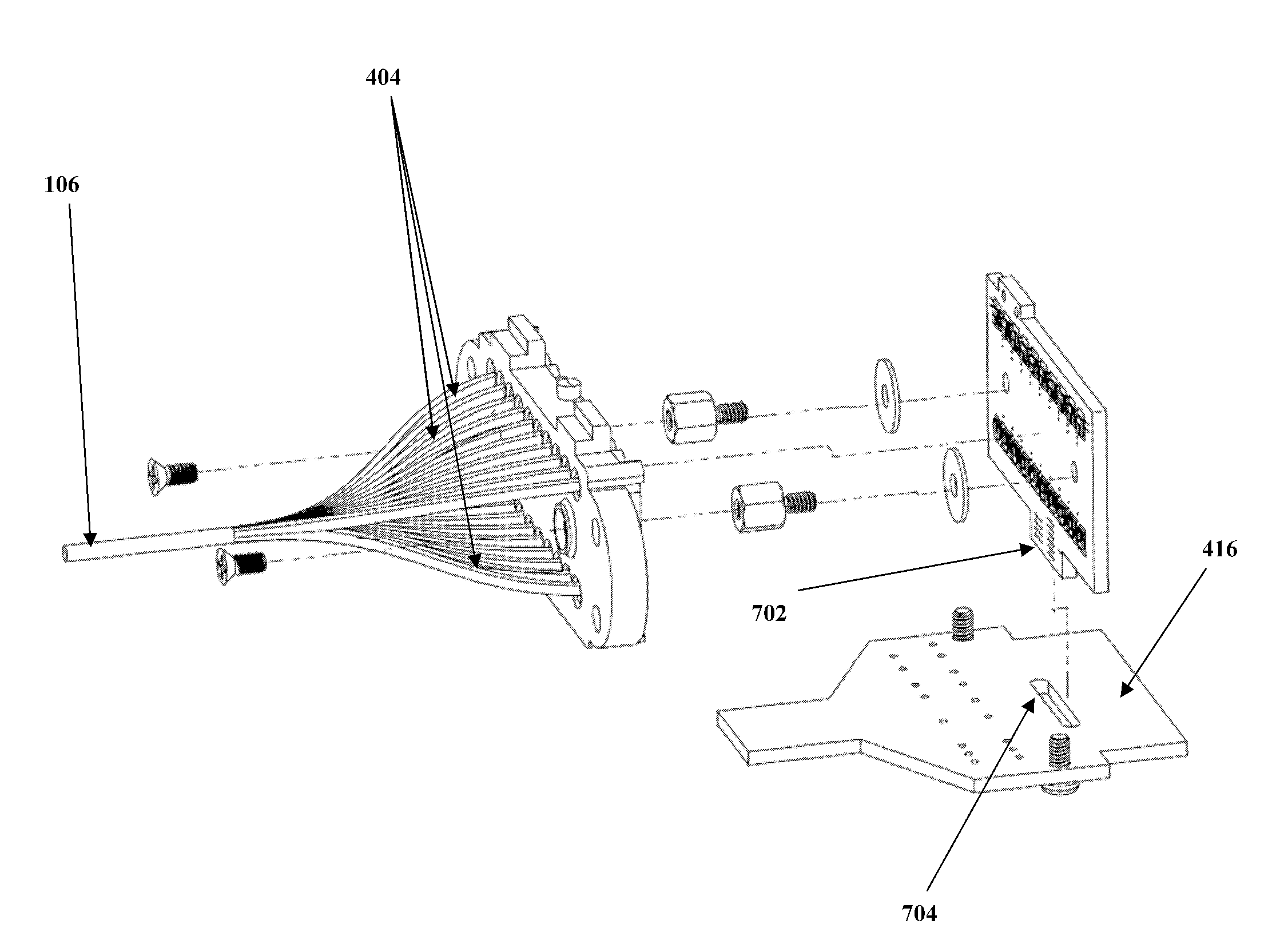
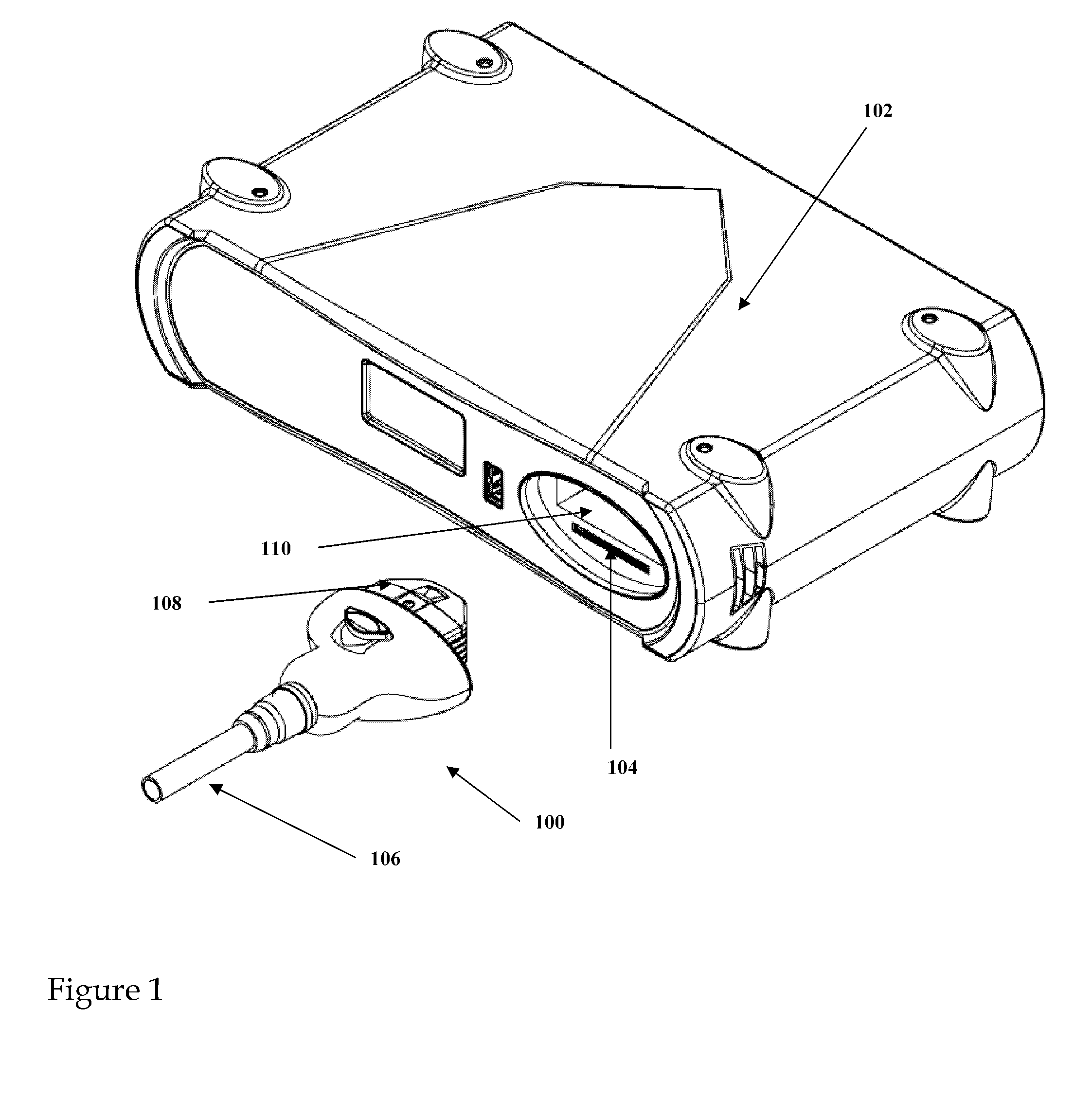
A high output light emitting diode (LED) based lighting module includes a plurality of LEDs on a substrate board, a fiber optic mounting assembly that securely holds a plurality of fiber bundles that form a fiber cable to said LEDs so that each LED mates to a fiber bundle making each fiber bundle slightly overlap the active area of its respective LED and mechanical means for holding each fiber optic bundle a fixed distance from said LED substrate.

Description

CROSS-REFERENCE TO RELATED APPLICATIONS[0001]This application claims priority to U.S. provisional patent applications Ser. No. 61 / 570,663 titled “Light Emitting Diode Cable” filed on Dec. 14, 2011, and Ser. No. 61 / 583,273 titled “Connector LED Heatsink” filed on Jan. 5, 2012 the disclosure of which is herein incorporated by reference in their entirety.PATENTS CITED[0002]The following documents and references are incorporated by reference in their entirety, Savage, Jr., (U.S. Pat. No. 5,548,676), Wehner (U.S. Pat. No. 7,086,765), Ruffin (U.S. Pat. No. 7,182,496), Gingrich, III et al (U.S. Pat. No. 7,942,563), Simon et al (U.S. Pat. No. 8,256,924) and Huang (U.S. Pat. Appl. No. 2012 / 0194071).FIELD OF THE INVENTION[0003]The present invention relates generally to the field of light emitting diodes and of efficient ways to remove the heat generated by their operation. More specifically, the present invention is directed to a lighting device that allows for the use of multiple LEDs to be ...

Claims


Application Information

Patent Timeline
Patent Type & Authority Patents(United States)
IPC IPC(8): H01L29/22
CPCH01L23/48A61B1/07G02B6/0005G02B6/0006H01L33/48H01L23/49H01L33/58A61B1/0684G02B6/4292G02B6/4269G02B6/4202H01L2924/0002G02B6/4249G02B6/00G02B6/4278G02B6/428H01L2924/00
Inventor SANSO, DAVIDWILLIAMS, MASONHYMEL, BRENTPITZER, AARON
Owner SANSO DAVID
Why Eureka
Try Eureka